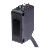
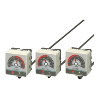
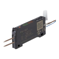
Slim Body Automatic Sensitivity Setting Photoelectric Sensor SU-7 SERIES SH SERIES
13
PRECAUTIONS FOR PROPER USE
Amplier
External synchronization function (SU-75 only)
• The external synchronization function can be used to
control the timing of sensing. Edge trigger or gate trigger
are available.
Note: The external synchronization selection switch must be turned fully
clockwise or counterclockwise.
Test input (emission halt) function (SU-75 only)
• When the test input (emission halt input) (violet) is short-
circuited to 0 V (Low), the beam emission is halted. This
function is useful for a start-up test since the sensing output
can be made ON/OFF without the sensing object. Short-circuit
to 0 V and open the input, repeatedly. If the sensing output
follows this operation, the sensor is working well, else not.
Low
ON
OFF
T ≥ 0.6 ms
st input
)
in the Dark-ON
mode
T ≥ 0.8 ms
when the interference
prevention function
is used
T T T
Timer function (Excluding SU-75)
• Every SU-7 series amplier (excluding SU-75) is incorporated
with a variable ON/OFF delay timer for 0 to 5 sec.
ON-delay
As only longer
signals are extracted,
this function is useful
for detecting if a line
is clogged, or for
sensing only objects
taking a long time to
travel.
OFF-delay
Since the output
signal is extended for
a xed time interval,
this function is useful
if the output signal
is so short that the
connected device
cannot respond.
Self-diagnosis function
• The sensor checks the incident light intensity, and if it is
reduced due to dirt or dust, or beam misalignment, an
output is generated.
Stable light received level
Sensing output threshold level
Sensing condition
Sensing output
(operation indicator
)
(in the Light-ON mode)
Stability indicator
Self-diagnosis output
Stable dark level
ON (Lights up)
OFF (Lights off)
Lights up
Lights off
OFF
ON
Insufficient beam intensity
Insufficient beam interruption
2
1 1
3
40 ms approx. 40 ms approx.
1
The self-diagnosis output transistor stays in the “OFF”
state during stable sensing.
2
When the sensing output changes, if the incident light
intensity does not reach the stable light received level or
the stable dark level, the self-diagnosis output becomes
ON. It is automatically restored after 40 ms approx.
Further, the self-diagnosis output changes state when the
sensing output changes from Light to Dark state.
It is not affected by the output operation of the sensing
output.
3
In case of insufcient beam interruption, there will be a
time lag before the self-diagnosis output turns ON.
Others
• Do not use during the initial transient time (0.5 sec.) after
the power supply is switched on.
• Timer period setting
Note: Adjust the timer under “SET” mode. Adjustment
is not allowed in “SIF” or “RUN” mode.
Adjust the time duration of ON or OFF
delay by turning the timer adjuster.
OND
OFD
0
sec.
sec.
condition
Operation
Normal
operation
ON-delay
OFF-delay
Normal
operation
ON-delay
OFF-delay
Timer period: T = 0 to 5 sec.
ON at the non-sensing state ON at the sensing state
Sensing
Non-
sensin
ON
OFF
ON
OFF
ON
OFF
ON
OFF
T
T T T
T
T
ON
OFF
ON
OFF
ON
OFF
ON
OFF
40 ms approx.
High
Low
T
ON
OFF
ON
OFF
High
Low
T
Edge trigger Gate trigger
Sensing
signal
T ≥ 0.6 ms (T ≥ 0.8 ms when the interference prevention function is used)
External
sync. input
Sensing
output
External sync.
selection switch
Place ferrite core at the sensor cable.
Place a ferrite core near the amplifier
.
In that condition, the sensor head cable should be single-winding.
Prepare
1 pc. of the following recommended ferrite core (or an
equivalent product.)
<Recommended product>
ESD-SR-110 [NEC TOKIN Corporation]
Amplifier
Ferrite core
Sensor head
Amplifier
Ferrite core
Sensor head
When sensor head is
reflective type
When sensor head is
thru-beam type
Use conditions to comply with CE Marking
(SH-3□ only)
• Following work must be done in cace of using this
product as a CE marking (European standard EMC
Directive) conforming product.
Downloaded from Arrow.com.Downloaded from Arrow.com.Downloaded from Arrow.com.Downloaded from Arrow.com.Downloaded from Arrow.com.Downloaded from Arrow.com.Downloaded from Arrow.com.Downloaded from Arrow.com.Downloaded from Arrow.com.Downloaded from Arrow.com.Downloaded from Arrow.com.Downloaded from Arrow.com.Downloaded from Arrow.com.

 Loading...
