10
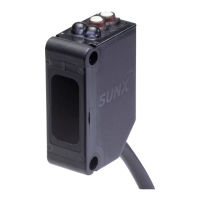
Slim Body Automatic Sensitivity Setting Photoelectric Sensor SU-7 SERIES SH SERIES
I/O CIRCUIT AND WIRING DIAGRAMS
SU-7P
Standard type/PNP output
I/O circuit diagram Wiring diagram
SENSING CHARACTERISTICS (TYPICAL)
SH-21 SH-21E
Thru-beam type
SH-31R
Thru-beam type
SH-31G
Thru-beam type
SH-33R
Thru-beam type
SH-22
Diffuse reective type
SH-32R
Diffuse reective type
SH-72
Glass substrate detection sensor
SH-82R
Mark sensor
SH-82G
Mark sensor
SH-84R
Mark sensor
Parallel deviation Parallel deviation Parallel deviation Parallel deviation
Sensing eld
Sensing eld
Sensing eld Sensing eld Sensing eld Sensing eld
Correlation between sensing object size and sensing range
As the sensing object size
becomes smaller than the
standard size (white non-glossy
paper 50 × 50 mm 1.969 ×
1.969 in), the sensing range
shortens, as shown in the left
graph.
For plotting the left graph,
the sensitivity has been set
such that a 50 × 50 mm 1.969
× 1.969 in white non-glossy
paper is just detectable at a
distance of 100 mm 3.937 in.
D
Z
D2
Tr 1
Tr 2
100 mA max.
50 mA max.
Load
Load
Z
D1
(Brown) +V
(Black) Sensing output
(Orange) Self-diagnosis
output
(Blue) 0 V
Users’ circuit Internal circuit
+
–
±10 %
Sensor circuit
Load
Load
Brown
Black
Orange
Blue
+
–
±10 %
100
3.937
50
1.969
0
50
1.969
100
0
0.5
1.640
1.0
3.281
Lℓ
Emitter
Receiver
Left
Right
Center
Setting distance L (m ft)
10
0.394
5
0.197
05
0.197
10
0
50
1.969
100
3.937
Lℓ
Receiver
Emitter
Left
Right
Center
Operating point ℓ (mm in)
Setting distance L (mm in)
Left
Right
Center
Operating point ℓ (mm in)
200
7.874
100
3.937
0 100
3.937
200
0
1
3.281
2
6.562
Lℓ
Emitter
Receiver
Setting distance L (m ft)
0
50 × 50 mm
1.969 × 1.969 in
White non-glossy paper
L
ℓ
Sensor
head
10
0.394
5
0.197
10
5
0.197
0
Left
Right
Center
Operating point ℓ (mm in)
20
0.787
40
1.575
3.150
60
2.362
Setting distance L (mm in)
100
3.937
20
0.787
40
1.575
60
2.362
80
50
1.969
L
a × a mm a × a in
White
non-glossy paper
White non-glossy paper
Sensor
head
0
Sensing range L (mm in)
10
0.394
5
0.197
05
0.197
10
0
50
1.969
100
3.937
L
ℓ
Sensor
head
50 × 50mm
1.969 × 1.969 in
White non-glossy
paper
Left
Right
Center
Operating point ℓ (mm in)
Setting distance L (mm in)
4
0.157
2
0.079
02
0.079
4
0
4
0.157
8
0.315
24 × 24 mm
0.945 × 0.945 in
Transparent glass plate
L
Center RightLeft
Sensor
head
Operating point ℓ (mm in)
ℓ
Setting distance L (mm in)
0
5
0.197
10
0.394
15
0.591
0.787
1
0.039
0.5
0.020
0 0.5
0.020
1
L
ℓ
9 mm
0.354 in
L
ℓ
50 × 50 mm
1.969 × 1.969 in
White non-glossy
paper
50
×
50 mm
1.969
×
1.969 in
White non-glossy paper
(Down) Left
Right (Up)
Center
Operating point ℓ (mm in)
Setting distance L (mm in)
Vertical direction
Horizontal
direction
Sensor
head
Sensor
head
Horizontal
direction
Vertical
direction
(Down) Left
Right (Up)
Center
Operating point ℓ (mm in)
0
5
0.197
10
0.394
15
0.591
0.787
1
0.039
0.5
0.020
0 0.5
0.020
1
L
ℓ
ℓ
L
9 mm
0.354 in
Horizontal
direction
Vertical
direction
50 × 50 mm
1.969 × 1.969 in
White non-glossy
paper
50
×
50 mm
1.969
×
1.969 in
White non-glossy paper
Setting distance L (mm in)
Vertical
direction
Horizontal
direction
Sensor
head
Sensor
head
0
10
0.394
20
0.787
30
1.181
1.575
4
0.157
2
0.079
02
0.079
4
L
ℓ
L
ℓ
9 mm
0.354 in
Horizontal
direction
Vertical
direction
50 × 50 mm 1.969 × 1.969 in
White non-glossy paper
(Down) Left
Right (Up)
Center
Operating point ℓ (mm in)
Setting distance L (mm in)
Vertical
direction
Sensor
head
Sensor
head
50 × 50 mm
1.969 × 1.969 in
White non-glossy
paper
Horizontal
direction
Lℓ
Receiver
Emitter
100
3.937
50
1.969
050
1.969
100
3.937
0
100
3.937
200
7.874
300
11.811
15.748
Left
Right
Center
Operating point ℓ (mm in)
Setting distance L (mm in)
Symbols … D: Reverse supply polarity protection diode
Z
D1
, Z
D2
: Surge absorption zener diode
Tr
1
, Tr
2
: PNP output transistor
Downloaded from Arrow.com.Downloaded from Arrow.com.Downloaded from Arrow.com.Downloaded from Arrow.com.Downloaded from Arrow.com.Downloaded from Arrow.com.Downloaded from Arrow.com.Downloaded from Arrow.com.Downloaded from Arrow.com.Downloaded from Arrow.com.

 Loading...