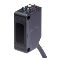
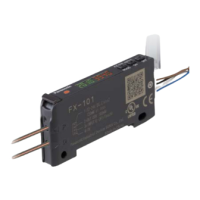
Slim Body Automatic Sensitivity Setting Photoelectric Sensor SU-7 SERIES SH SERIES
9
Black
Orange
Blue
Pink
Violet
Load
Load
*1
+
–
±10 %
I/O CIRCUIT AND WIRING DIAGRAMS
SU-7 SU-7J
Standard type/NPN output
I/O circuit diagram Wiring diagram
D
Sensor circuit
Internal circuit Users’ circuit
ZD1
ZD2
Tr1
Tr2
(Brown) +V
100 mA max.
50 mA max.
Load
Load
±10 %
+
–
(Black)
Sensing output
(Blue) 0 V
(Orange) Self-diagnosis output
Brown
Black
Orange
Blue
Load
Load
+
–
±10 %
SU-77
Remote sensitivity setting type
I/O circuit diagram Wiring diagram
D
Sensor circuit
Internal circuit
Users’ circuit
ZD1
ZD2
5 V
10 kΩ
10 kΩ
5 V
Tr1
Tr2
(Brown) +V
100 mA max.
50 mA max.
Load
Load
±10 %
(Black) Sensing output
(Pink) Remote sensitivity ON input
Remote sensitivity
OFF input
(Blue) 0 V
(Orange) Self-diagnosis output
Prevent wrong setting by
installing a switch to control
effectiveness of setting switch
(Violet)
+
–
+
–
±10 %
Black
Orange
Pink
Violet
*1
Load
Load
* 1
SU-75
External synchronization input type
I/O circuit diagram Wiring diagram
D
Sensor circuit
Internal circuit Users’ circuit
ZD1
ZD2
Tr2
5 V
10 kΩ
10 kΩ
5 V
Tr1
(Brown) +V
100 mA max.
50 mA max.
Load
Load
±10 %
+
–
(Black) Sensing output
(Pink) External synchronization input
(Violet) Test input (emission halt)
(Blue) 0 V
(Orange) Self-diagnosis output
Black
Orange
Pink
Violet
Load
Load
*1
+
–
±10 %
* 1
Non-voltage contact or
NPN open-collector transistor
or
• External synchronization input/test input.
Low: 0 to 1 V
High: 4.5 to 30 V, or open
SU-79
Remote sensitivity selection type
I/O circuit diagram Wiring diagram
Z
D2
Tr 1
Tr 2
100 mA max.
50 mA max.
Z
D1
Sensor circuit
Users’ circuit Internal circuit
(Brown) +V
(Pink) Remote sensitivity selection input 1
Remote sensitivity
selection input 2
(Black) Sensing output
(Orange) Self-diagnosis output
(Blue) 0 V
D
5 V
10 kΩ
5 V
10 kΩ
Load
Load
±10 %
(Violet)
+
–
* 1
Symbols … D: Reverse supply polarity protection diode
Z
D1
, Z
D2
: Surge absorption zener diode
Tr
1
, Tr
2
: NPN output transistor
Symbols … D: Reverse supply polarity protection diode
Z
D1
, Z
D2
: Surge absorption zener diode
Tr
1
, Tr
2
: NPN output transistor
Symbols … D: Reverse supply polarity protection diode
Z
D1
, Z
D2
: Surge absorption zener diode
Tr
1
, Tr
2
: NPN output transistor
Symbols … D: Reverse supply polarity protection diode
Z
D1
, Z
D2
: Surge absorption zener diode
Tr
1
, Tr
2
: NPN output transistor
Non-voltage contact or
NPN open-collector transistor
or
• Remote sensitivity ON input/OFF input.
Low: 0 to 1 V
High: 4.5 to 30 V, or open
Non-voltage contact or
NPN open-collector transistor
or
• Remote sensitivity selection input 1/2
Low: 0 to 1 V
High: 4.5 to 30 V, or open
Downloaded from Arrow.com.Downloaded from Arrow.com.Downloaded from Arrow.com.Downloaded from Arrow.com.Downloaded from Arrow.com.Downloaded from Arrow.com.Downloaded from Arrow.com.Downloaded from Arrow.com.Downloaded from Arrow.com.

 Loading...
