11.2. Initialization Pulse Adjust
1. Input the White signal to plasma video input.
2. Set the picture controls as follows.
Picture menu : Dynamic
PNR : OFF
Aspect : 16:9
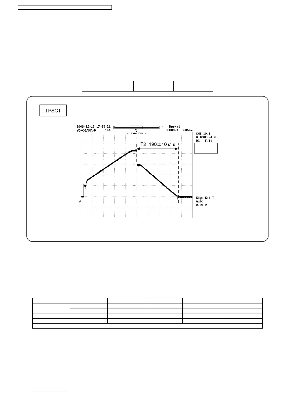
3. Connect Oscilloscope to TPSC1 (SC).
Check and adjust that the stand down pulse(T2) period are each within specification.
Test point Volume Level
T2 TPSC1 (SC) VR6602 (SC) 190 ± 10µ Sec
11.3. P.C.B. (Printed Circuit Board) exchange
11.3.1. Caution
1. To remove P.C.B. , wait 1 minute after power was off for discharge from electrolysis capacitors.
11.3.2. Quick adjustment after P.C.B. exchange
Adjust the following voltages with the multimeter.
P.C.B. Name Test Point Voltage Volume Remarks
P Board Vsus TPVSUS (SS) Vsus ± 2V R628 (P) *
PFC C446 396V ± 0.5V R443 (P)
SC Board Vad TPVAD (SC) -105V ± 1V VR6600 (SC)
SS Board Ve TPVE (SS) Ve ± 1V VR6000 (SS) *
D, DG Board White balance and Sub brightness for NTSC, PAL, HD, PC and 625i signals
*See the Panel label.
Caution:
Absolutely do not reduce Vsus below Ve not to damage the P.C.B.
28
TH-42PX7A / TH-42PV7AZ / TH-42PV7HS / TH-42PV7M / TH-42PV7MR