8
Connections
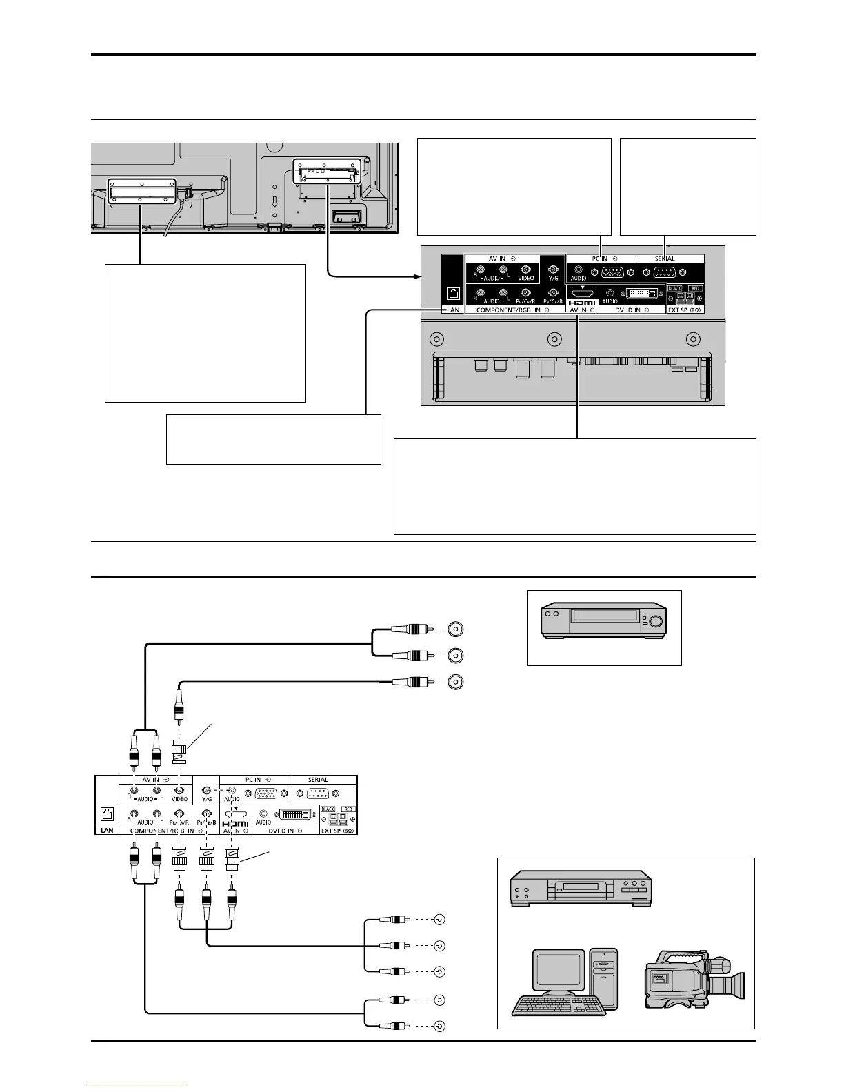
VIDEO and COMPONENT / RGB IN connection
Video equipment connection
SLOT: Terminal board (optional
accessories) insert slot (see
page 3)
Note:
The right side slot is for terminal
board with 2-slot width. The
terminal board with 1-slot width
does not function when installed
in the right side slot.
LAN: Connect to a network to control
the unit. (see page 19)
AV IN (VIDEO): Composite Video Input Terminal (see below)
COMPONENT/RGB IN: Component/RGB Video Input Terminal
(see below)
AV IN (HDMI): HDMI Input Terminal (see page 9)
DVI-D IN: DVI-D Input Terminal (see page 9)
Connect to video equipment such as VCR or DVD player.
PC IN:
PC Input Terminal
Connect to video
terminal of PC or
equipment with Y, P
B
(C
B
)
and P
R
(C
R
) output
(see page 10).
SERIAL: Control the
Plasma
Display by
connecting
to PC (see
page 11)
, Y , P B , P R
OUT
P
R
P B
Y
AUDIO
OUT
R
L
VIDEO
OUT
AUDIO
OUT
R
L
Notes:
• Change the “Component/RGB-in select” setting in the “Setup”
menu to “Component” (when Component signal connection) or
“RGB” (when RGB signal connection).
• Accepts only RGB signals with “Sync on G”.
RCA-BNC
Adapter plug
RCA-BNC
Adapter plug
DVD Player
VCR
Computer RGB Camcorder
Note:
Additional equipment, cables and adapter plugs
shown are not supplied with this set.
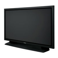
Ex. TH-65PF20ER
 Loading...