Home
Panasonic
Camcorder
VDR-D100
Page 22 (Service Position)
Panasonic VDR-D100 - Service Position
90 pages
Manual
Save Page as PDF
To Next Page
To Next Page
To Previous Page
To Previous Page
Loading...
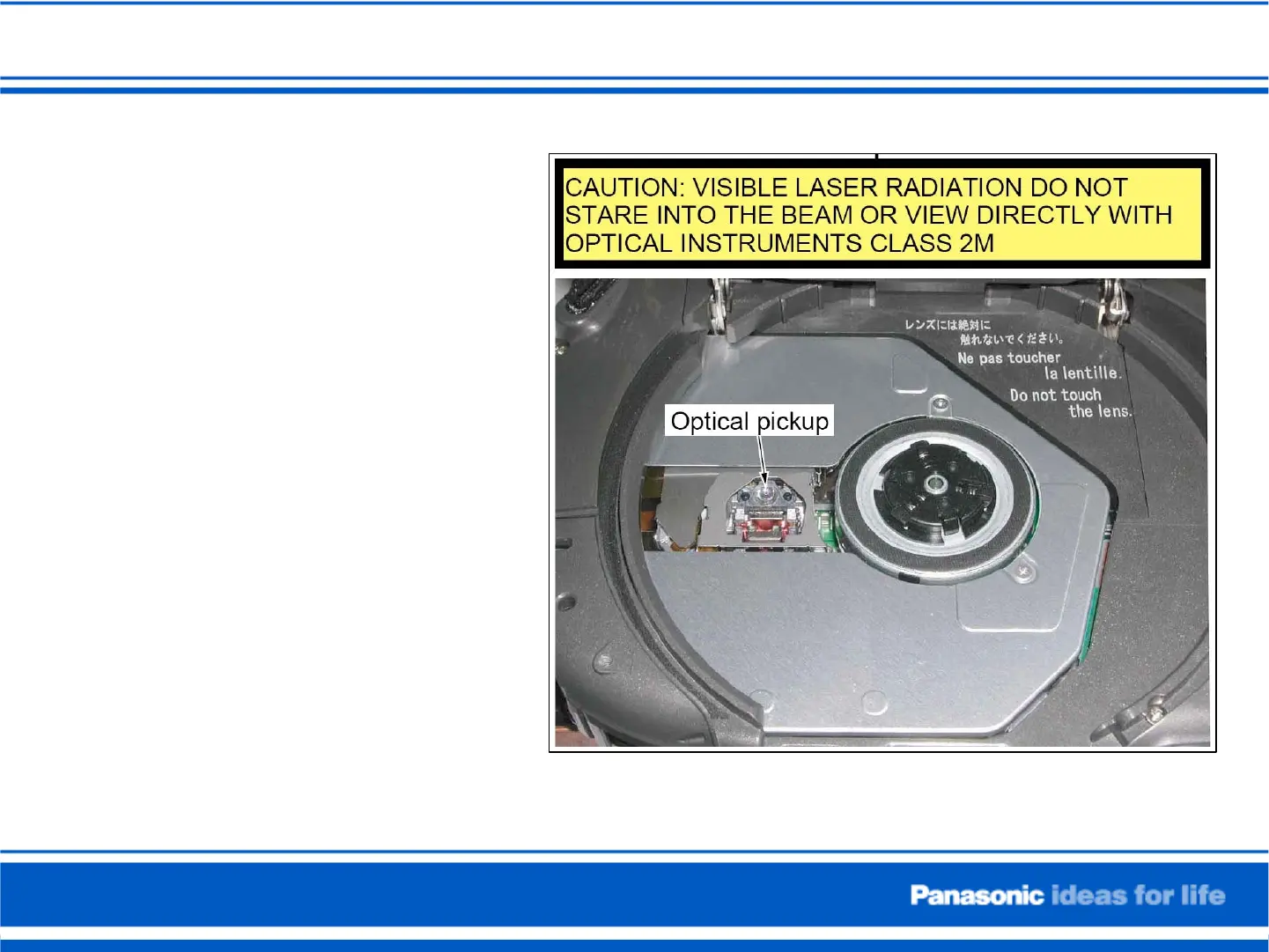
Service Position
Staring at the light from the
laser may cause eyesight loss.
For safety, be sure to remove
any power supply (AC adaptor
or battery) from the DVD video
Camera before beginning to
work on the camera.
21
23
Table of Contents
Main Page
DVD/DVC Camera Seminar VDR-D100/200/300 and PV-GS29/39
1
Features (VDR-D100~300)
2
DVD Camera Comparison
3
Recording/Playback Media (DVD Camera)
4
Discs that can not be used in this unit
5
Camera Structure VDR-D100/200
6
Camera Structure VDR-D300
7
Camera Structure VDR-D300
8
Extension Cables for VDR-D100-200
9
Extension Cables for VDR-D300
10
Light box, Charts, etc for all DVD Cameras
11
Slide Number 12
12
Reset
13
Service Mode
14
Service Mode
15
DVD Drive/Camera information
16
List of Error Codes
17
How to Read The Error History
18
Troubleshooting hint for DVD Error Code
19
Troubleshooting hint for Camera Error Code
20
Troubleshooting Hint
21
Service Position
22
How to Eject the DVD Tray Manually
23
Service Position VDR-D100/200
24
Service Position II
25
Auto Ground-directional Standby (AGS) (VDR-D300 only)
26
To turn the AGS function on/off
27
Update Procedure for ARM FW
28
Update Procedure for ARM FW
29
Update Procedure for FW
30
Update Procedure for FW
31
Update Procedure for FW
32
Update Procedure for FW
33
Update Procedure for FW
34
Update Procedure for DVD Drive F/W
35
Update Procedure for DVD Drive F/W
36
Update Procedure for DVD Drive F/W
37
Update Procedure for DVD Drive F/W
38
Service Mode (Version Check)
39
Service Mode (F/W Version Check)
40
Service Mode (F/W Version Check)
41
Troubleshooting
42
VDR-D100/105/200 IC/Connectors Location
43
VDR-D100/105/200 IC/Connectors Location
44
VDR-D300 IC/Connectors Location
45
VDR-D300 IC/Connectors Location
46
VDR-D300 IC/Connectors Location
47
VDR-D300 IC/Connectors Location
48
System Control (VDR-D100/105/200)
49
Standby Circuit (VDR-D100/105/200)
50
Power Supply Components Location
51
Power ON (VDR-D100/105/200)
52
Power ON (VDR-D100/105/200)
53
Overall Diagram (VDR-D300)
54
Camera Video 1 (VDR-D300)
55
Video Signal Process (VDR-D300)
56
Digital Signal Process (VDR-D300)
57
Audio Video Processor (VDR-D300)
58
DVC Camera
59
Service Menu
60
Service Menu
61
Service Menu
62
Service Menu
63
Slide Number 64
64
Slide Number 65
65
Slide Number 66
66
Slide Number 67
67
Slide Number 68
68
Slide Number 69
69
Slide Number 70
70
Slide Number 71
71
Slide Number 72
72
Slide Number 73
73
Slide Number 74
74
PC-EVR Adjustment Program Set-up
75
PC-EVR Adjustment Program Set-up
76
Main PCB (Foil Side) PV-GS29, 36, 39, 59
77
Overall Block Diagram PV-GS29, 36, 39, 59
78
Overall Block Diagram PV-GS29, 36, 39, 59
79
Overall Block Diagram PV-GS29, 36, 39, 59
80
System Control Block PV-GS29, 36, 39, 59
81
STB Block PV-GS29, 36, 39, 59
82
TP20 (+Batt.) Test Point Location
83
Power On Block PV-GS29, 36, 39, 59
84
TP15 (Power On (L)) Test Point Location
85
Video Signal Process PV-GS29, 36, 39, 59
86
Video Signal Output Test Point Location
87
PLAY/REC. Signal (PV-GS29, 36, 39, 59 )
88
PLAY Signal TP (PV-GS29, 36, 39, 59 )
89
Slide Number 90
90
Related product manuals
Panasonic VDR-D100EB
120 pages
Panasonic Palmcorder VDR-D100
160 pages
Panasonic VDR-D150EE
116 pages
Panasonic VDR-D150GN
116 pages
Panasonic VDR-D160GN
116 pages
Panasonic VDR-D150EB
120 pages
Panasonic VDR-D160GC
232 pages
Panasonic VDR-D50
105 pages
Panasonic VDR-D310
12 pages
Panasonic vdr-d300
203 pages
Panasonic VDR VDR-D220
124 pages
Panasonic DVD e.cam VDR VDR-D210
156 pages