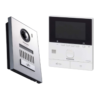
YES
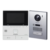
YES
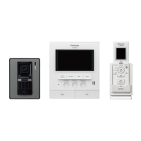
YES
NO
No image can be seen by the call from the Door Station.
(The ringer tone and the talking are OK.)
Measuring conditions (FM signal):
The Main Monitor Station and
the Door Station should be connected.
Supply power to the Main Monitor Station,
and press “TALK” Button of the Main Monitor Station.
Then make sure that an FM signal
has arrived at pin 3 of IC200.
Is there Image signal
at TD200 (Main Board) OK?
(Refer to Fig.2)
Check around IC200
(Main Board).
Are there any faulty
parts found?
Replace Camera (CMOS) Ass'y
Replace the fault parts.
NO
NO
Replace the Main board.
NO
C
Is the FM signal at
pin3 of IC200 on the Main Board of
the Door Station OK?
(Refer to Fig.1)
Check Signal Flow of the Image Signal
(Door Station) Main Board
Replace the fault parts.
The FM signal from pin3 of IC200 on the Main Board of the Door Station.
The image signal (TD200) from the Camera (CMOS) of the Door Station.
Measuring conditions (Image signal):
The Main Monitor Station and the Door Station should be connected.
Supply AC Power to the Main Monitor Station, and press “TALK” Button of the Main Monitor Station.
Then make sure that a signal has arrived at IC200.
* The signal level and waveform can be changed significantly depending on the capturing subject.
It is OK when the same signal shape in the circle is confirmed (No concern with the voltage level.).
About 1.7 V
Fig.1 FM signal
Fig.2 Image signal
 Loading...