EasyManua.ls Logo

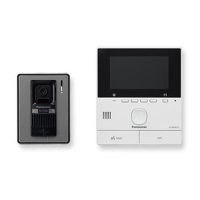
Panasonic VL-SVN511BX - User Manual

Panasonic VL-SVN511BX
88 pages
To Next Page IconTo Next Page
Loading...
© Panasonic Corporation 2019
Unauthorized copying and distribution is a violation
of law.
ORDER NO. KMA1511067CE
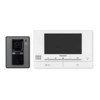
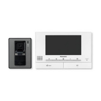
Video Intercom System
Model No. VL-SVN511BX
VL-MVN511BX
VL-V522LCE
VL-RLY1
VL-PS241
Model No. VL-SVN511CX
Model No. VL-SVN511CX1
VL-MVN511BX
VL-V522LCE
VL-RLY1
VL-PS241
(BX: for Asia, Middle Near East and Africa)
(CX: for Middle East and Hong Kong)
(CX1: for UAE)
[Version 2.0]

Table of Contents

Questions and Answers:

Panasonic VL-SVN511BX Specifications

General IconGeneral
BrandPanasonic
ModelVL-SVN511BX
CategoryIntercom System
LanguageEnglish

Summary

Safety Precautions

General Safety and Technician Guidelines

Essential safety practices for servicing, including electrical hazards and technician responsibilities.

Product Warnings and Solder Information

Lead-Free Solder Handling and Precautions

Guidance on using lead-free solder, including melting points and suggested types.

Repair and Board Handling Notes

Procedures for insulation resistance testing, PCB disposal, and general repair notes.

System Specifications

Main Monitor Station Specifications

Detailed specifications for the VL-MVN511 main monitor station.

Peripheral Unit Specifications

Specifications for power supply, relay box, and door station units.

Technical Descriptions

What is a Video Intercom?

Explains the basic concept and benefits of a video intercom system.

Video Intercom System Block Diagram and Signal Flow

Details the system's block diagram and signal paths for image and voice.

IC Operations and Diagrams

Monitor Station IC Operations and Schematics

Details IC functions and schematic breakdowns for the monitor station.

Door Station and Peripheral IC Operations

Explains IC functions and diagrams for door station and relay box.

Installation and Operation Guides

Controls, Installation, and Operation

Locating controls, installation steps, and operating procedures for the system.

Troubleshooting Procedures

Door Station Troubleshooting

Step-by-step guide for diagnosing door station operational issues.

Main Monitor Station Operation Checks

Troubleshooting common issues with the main monitor station's operation.

Component-Specific Troubleshooting

Diagnosing defects in power supply, WiFi, video, communication, and locks.

Error Messages and Signal Routes

Lists error messages and provides signal flow tracing procedures.

Disassembly and Assembly Instructions

Main Monitor Station Disassembly Procedures

Procedures for disassembling the main monitor station's components.

Door Station Disassembly and Assembly Notes

Steps for disassembling and reassembling the door station, including camera adjustment.

Power Supply and Relay Box Component Removal

Instructions for removing the power supply unit and relay box components.

Measurements and Adjustments

Main Monitor Station Calibration and IC Replacement

Detailed steps for connections, IC replacement, factory mode, and adjustments.

Miscellaneous Procedures

Flat Package IC Replacement Guide

Method for replacing flat package ICs using basic tools and procedures.

Schematic Diagrams

Main Monitor Station Schematics

Detailed schematics for the main monitor station's main and power boards.

Peripheral Unit Schematics

Schematics for door station, power supply unit, and relay box.

Printed Circuit Board Layouts

Main Monitor Station PCB Layouts

Component and bottom views of the main monitor station's PCBs.

Door Station and Peripheral PCB Layouts

PCB layouts for door station, power supply, and relay box.

Exploded Views and Parts Lists

Exploded Views of System Components

Visual breakdown of system components for identification and assembly.

Replacement Parts Identification

Comprehensive list of part numbers and descriptions for all system components.

Document Change Information

Revision History

Records changes and version updates made to the service manual.

Related product manuals