9
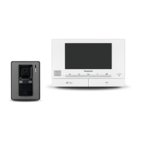
VL-SVN511BX/VL-SVN511CX/VL-SVN511CX1
4 Technical Descriptions
4.1. What is a Video Intercom?
4.2. Video Intercom
4.2.1. Block Diagram
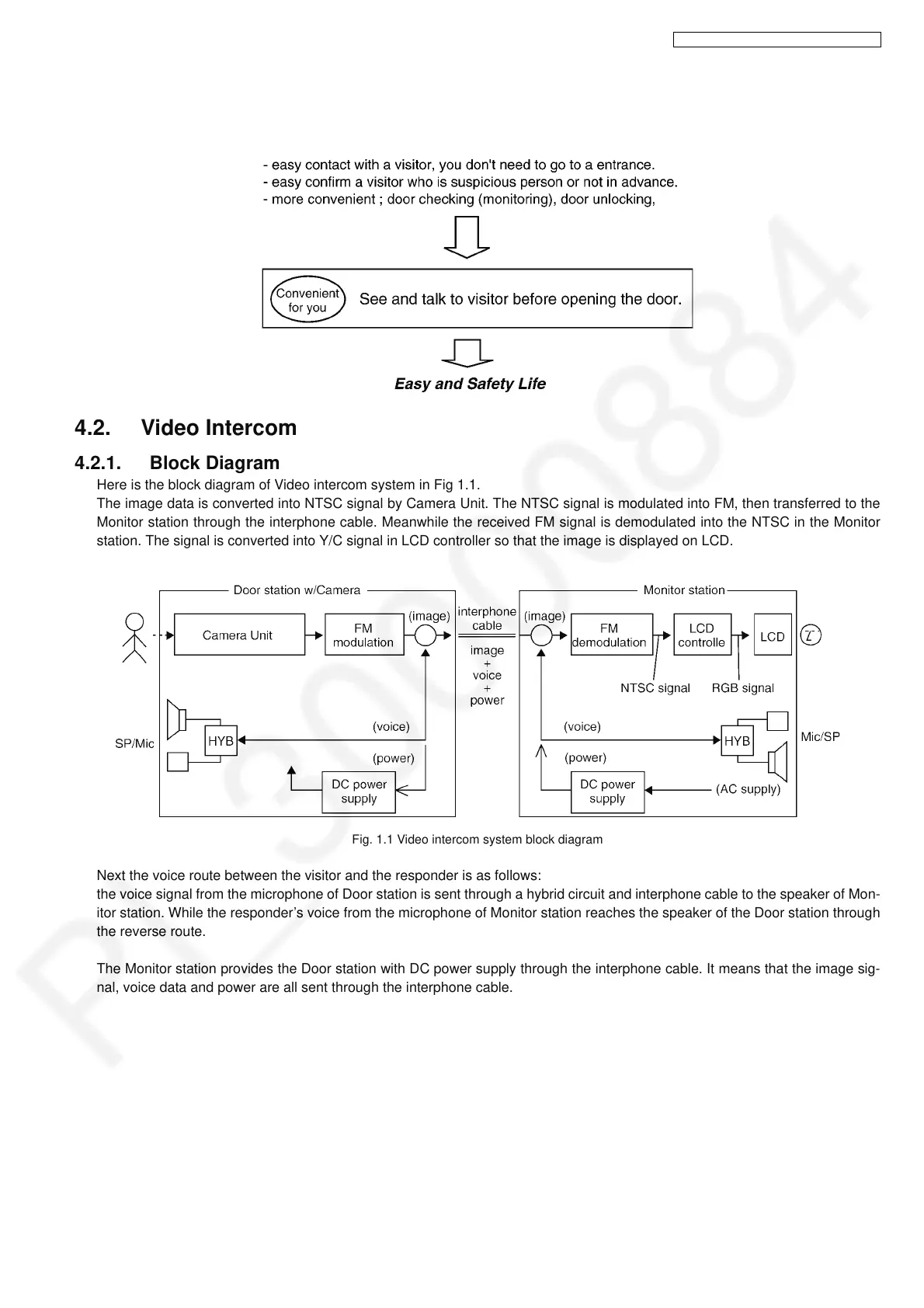
Here is the block diagram of Video intercom system in Fig 1.1.
The image data is converted into NTSC signal by Camera Unit. The NTSC signal is modulated into FM, then transferred to the
Monitor station through the interphone cable. Meanwhile the received FM signal is demodulated into the NTSC in the Monitor
station. The signal is converted into Y/C signal in LCD controller so that the image is displayed on LCD.
Fig. 1.1 Video intercom system block diagram
Next the voice route between the visitor and the responder is as follows:
the voice signal from the microphone of Door station is sent through a hybrid circuit and interphone cable to the speaker of Mon-
itor station. While the responder’s voice from the microphone of Monitor station reaches the speaker of the Door station through
the reverse route.
The Monitor station provides the Door station with DC power supply through the interphone cable. It means that the image sig-
nal, voice data and power are all sent through the interphone cable.
 Loading...