Do you have a question about the Panasonic VL-SV75 Series and is the answer not in the manual?
Repair services must follow manual guidelines to prevent hazards.
Test to prevent electrical shock hazard by measuring resistance.
Ensure power outlet is accessible and near the equipment.
Warning regarding incorrect battery types and proper disposal.
Guidelines and precautions for using lead-free solder in repairs.
Instructions for deleting personal data before discarding P.C. boards.
Advise users on potential data loss and handling personal data during repair.
Proper disposal methods for used electrical and electronic products.
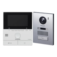
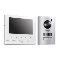
Details power, dimensions, mass, environment, and display for the main monitor.
Details power, dimensions, mass, environment, viewing angle, and illuminance.
Details input/output power, dimensions, mass, and environment for the power supply.
Diagram illustrating image, voice, and command signal flow paths.
Identifies ICs and their connections within the monitor station.
Information on regulators, FM demodulation, OP AMPs, and photo couplers.
Details on Sub CPU, FROM, EEPROM, and SRAM ICs.
Details on OP AMP for LCD_BL and Timer ICs.
Details on DPJP3, SDRAM, and FLASH MEMORY ICs.
Details on the 12V Regulator for the power board.
Details on 3.3V Regulator and Touch Button Controller.
Details on the Power control IC for the power supply unit.
Diagram illustrating ICs and connections within the door station.
Details on Call Button, FM Modulator, Regulator, Amplifiers, MCU, and Sensor ICs.
Refer to Operating Instructions for control and component locations.
Refer to Operating Instructions for installation procedures.
Refer to Operating Instructions for system operation.
Procedures for initializing and adjusting main monitor after IC replacement.
Flowchart for troubleshooting door station operational issues.
Troubleshooting steps for main to extension monitor communication failures.
Troubleshooting steps for issues with extension monitor video recording.
Troubleshooting steps for power supply unit defects in the main monitor.
Troubleshooting steps for main monitor video recording issues.
Troubleshooting steps for main monitor to door station communication failures.
Troubleshooting steps for extension monitor to door station communication failures.
Troubleshooting steps for key board unit issues.
Guidelines for tracing signals through PCBs to identify faulty points.
Procedure for detaching the DC cable from the main monitor.
Procedure for detaching the main monitor's cabinet cover.
Procedure for detaching the main board, speaker, and LCD.
Procedure for detaching the power board and key board.
Procedure for detaching the front panel of the door station.
Procedure for removing the door station unit from its mounting.
Procedure for detaching the main board and camera unit.
Procedure for detaching the mic board and speaker.
Procedure for removing the power board from the power supply unit.
Connection points and items for main board adjustments.
Preparation and test points for BBIC and X'tal adjustments.
Steps to access the main monitor's factory mode.
Steps to initialize logs, parameters, and delete recorded images.
Procedure for adjusting LCD color balance after screen replacement.
Configuration for connecting to large apartment intercom systems.
Confirmation checks for door station functionality post main board replacement.
Preparation for replacing flat package ICs, including tools and materials.
Detailed steps for removing flat package ICs from the PCB.
Detailed steps for installing flat package ICs onto the PCB.
Procedure for modifying bridged connections on the PCB.
Schematic for the Main Board's external interface.
Schematic for the Main Board's BBIC section.
Schematic for the Main Board's DPJP3 and Key sections.
Schematic for the Main Board's LCD section.
Schematic for the Main Board's electric lock interface.
Schematic for the Main Board's DCDC converters.
Schematic for the Main Board's AM communication base unit.
Schematic for the Main Board's AM communication add base unit.
Schematic for the Main Board's Key section.
Schematic for the Power Board.
Schematic for the Door Station's main board.
Schematic for the Door Station's MIC board.
Schematic for the Power Supply Unit's power board.
Component layout of the main monitor station main board.
Bottom view component layout of the main monitor station main board.
Component and bottom views of the main monitor station key board.
Component and bottom views of the main monitor station power board.
Component and bottom views of the door station main board.
Component and bottom views of the door station MIC board.
Component layout of the power supply unit power board.
Bottom view of the power supply unit power board.
Exploded view of the main monitor station assembly.
Exploded view of the door station assembly.
Exploded view of the power supply unit assembly.
Exploded view of accessories and packing materials for VL-SV75AZ.
Exploded view of accessories and packing materials for VL-MV75AZ.
Exploded view of accessories and packing materials for VL-MV75AZA/BXA.
List of cabinet and electrical replacement parts for the main monitor station.
Replacement ICs and transistors for the main monitor station P.C. board.
Replacement diodes, varistors, connectors, and coils for the main monitor station P.C. board.
Replacement microphones, relays, switches, transformers, oscillators, and resistors.
Replacement resistors for the main monitor station P.C. board.
Replacement resistors and capacitors for the main monitor station P.C. board.
Replacement capacitors for the main monitor station P.C. board.
Replacement capacitors for the main monitor station P.C. board.
Final replacement parts for the main monitor station P.C. board.
List of replacement parts for the Key Board.
List of replacement parts for the Power Board.
List of cabinet and electrical replacement parts for the door station.
Replacement ICs, transistors, diodes, and LEDs for the door station main P.C. board.
List of replacement resistors and capacitors for the door station MIC P.C. board.
List of cabinet and electrical replacement parts for the power supply unit.
Replacement parts for the power supply unit P.C. board.
Exploded view of accessories and packing materials for VL-SV75AZ.
Exploded view of accessories and packing materials for VL-MV75AZ.
Exploded view of accessories and packing materials for VL-MV75AZA/BXA.
List of fixtures and tools used for installation or maintenance.
| Brand | Panasonic |
|---|---|
| Model | VL-SV75 Series |
| Category | Intercom System |
| Language | English |