n Connecting an optional lobby station
(VL-SVN511AZ models only)
MAIN MONITOR
<Rear view>
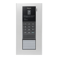
Lobby station
(VL-V590)
<Rear view>
NP
NP
NP
1
2
D1
D2
3
4
D3
D4
5
6
R1
R2
7
8
R3
IN1
9
10
IN2
IN3
11
12
IN4
P1
13P2
R1
1
R2 R3
S2
1
S1 S4
2
S3
2
Electric lock
30 V AC/
24V DC
Power
supply
NP: Non-polarised
RELAY BOX
<Connecting an optional lobby station for apartment complexes>
R B
e
sure to perform the following to ensure proper operation
– Connect terminal D1/D2 on the main monitor with terminal D1/D2 on the lobby station.
– Connect terminal R1/R2 on the main monitor with terminal R1/R2 on the Relay box.
– Connect terminal S1/S2 on the Relay box with terminal S1/S2 on the lobby station.
– After connecting to the main monitor, change the [Lobby connection] setting to [Connected devices]
using the main monitor. (®Operating Instructions of the Video Intercom System.)
R For information about lobby station connections, refer to the manuals of the lobby station.
7
 Loading...