EasyManua.ls Logo

Panasonic WH-SHF09F3E5 User Manual

Panasonic WH-SHF09F3E5
142 pages
To Next Page IconTo Next Page
Page #1 background imageLoading...
Page #1 background image
© Panasonic Corporation 2014.
Order No. PAPAMY1402032CE
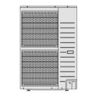
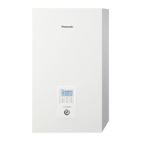
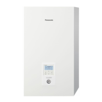
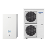
Indoor Unit Outdoor Unit
WH-SHF09F3E5
WH-SHF12F6E5
WH-UH09FE5
WH-UH12FE5
Destination
Europe
PRECAUTION OF LOW TEMPERATURE
In order to avoid frostbite, be assured of no refrigerant leakage during the installation or repairing of refrigerant circuit.
WARNING
This service information is designed for experienced repair technicians only and is not designed for use by the general public.
It does not contain warnings or cautions to advise non-technical individuals of potential dangers in attempting to service a product.
Products powered by electricity should be serviced or repaired only by experienced professional technicians. Any attempt to
service or repair the products dealt with in this service information by anyone else could result in serious injury or death.

Table of Contents

Questions and Answers:

Panasonic WH-SHF09F3E5 Specifications

General IconGeneral
BrandPanasonic
ModelWH-SHF09F3E5
CategoryHeat Pump
LanguageEnglish

Summary

Safety Precautions

Specifications

Model Specifications (WH-SHF09F3E5/WH-UH09FE5)

Detailed specifications for the WH-SHF09F3E5 and WH-UH09FE5 models.

Model Specifications (WH-SHF12F6E5/WH-UH12FE5)

Detailed specifications for the WH-SHF12F6E5 and WH-UH12FE5 models.

Features

Controls and Components Location

Indoor Unit Controls Overview

Identifies indoor unit controls and panel layout.

Adjusting Initial Settings and Usage

Guides on initial settings and basic operation functions.

Dimensions

Indoor Unit Dimensions

Provides dimensional drawings and measurements for the indoor unit.

Outdoor Unit Dimensions

Provides dimensional drawings and measurements for the outdoor unit.

Refrigeration and Water Cycle Diagram

Block Diagram

Wiring and Circuit Diagrams

Indoor Unit Wiring & Circuits

Wiring and electronic circuit diagrams for the indoor unit.

Outdoor Unit Wiring & Circuits

Wiring and electronic circuit diagrams for the outdoor unit.

Printed Circuit Board Layouts

Indoor Unit PCBs

Main and optional solar PCB layouts for the indoor unit.

Outdoor Unit PCBs

Main PCB layout for the outdoor unit.

Installation Instructions

Location Selection and Unit Mounting

Guidelines for selecting location and mounting indoor/outdoor units.

Piping and Drain Hose Installation

Procedures for installing refrigerant and water piping, and drain hose.

Electrical Cable Connections

Procedures for connecting electrical cables to both units.

System Evacuation and Pipe Prep

Procedures for refrigerant system evacuation and pipe cutting/flaring.

Operation and Control

Basic Operation Modes

Explains heating, tank, and heat+tank modes.

Water Pump and Safety Controls

Explains water pump control, safety features, and indicators.

Specialized Operation Modes

Details sterilization, quiet, anti-freeze, solar, and thermostat controls.

Protection Control

General Operation Protection

Covers time delay, current, and compressor overheating protection.

Heating Operation Protection

Details protection controls specific to heating, including deice operation.

Servicing Guide

Component Removal Procedures

Steps for removing front plate, side cabinet, and pump down.

Service Mode Operations

How to adjust flow rate, dry concrete, and perform EEPROM setup.

Maintenance Guide

Regular Unit Checks

Covers water pressure, relief valve, air purge, and control board checks.

Component Maintenance Procedures

Procedures for resetting overload protector and cleaning external filter.

Troubleshooting Guide

Refrigeration Cycle & System Conditions

Diagnosing issues within the refrigeration cycle and relating conditions to pressure/current.

Breakdown Self Diagnosis & Error Codes

How to access, interpret error codes, and perform self-diagnosis.

Specific Malfunction Troubleshooting

Detailed troubleshooting steps for various component errors (e.g., sensors, pumps, valves).

Disassembly and Assembly

Internal Component Removal

Steps for removing control panel, RCCB, transformer, and electronic board.

Valve, Pump & Bottle Removal

Steps for removing pressure relief valve, flow switch, air purge valve, water pump, and bottle.

Technical Data

Operation Characteristics

Graphs showing capacity and input power vs. temperature/piping length.

Heating Capacity Tables

Tables detailing heating capacity and input power.

Usage Limitations

Defines the operational limits of the unit.

Exploded Views & Parts List

Parts List (WH-SHF Series)

Exploded view and parts list for WH-SHF09F3E5/WH-SHF12F6E5.

Parts List (WH-UH Series)

Exploded view for WH-UH09FE5/WH-UH12FE5 units.

Related product manuals