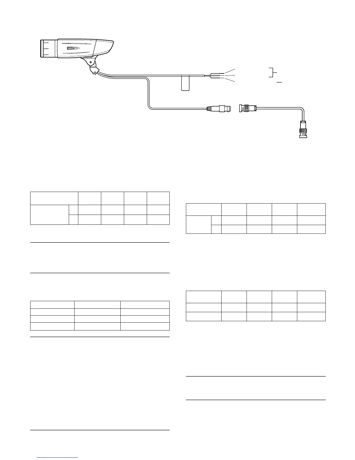
vMake a connection
Recommended
maximum cable
length
RG-15/U
(10C-2V)
800
RG-11/U
(7C-2V)
RG-6/U
(5C-2V)
RG-59/U
(3C-2V)
Type of coaxial cable
m
ft 2 640
600
1 980
500
1 650
250
825
Power connection
Caution:
• The following connections should be made by qualified
service personnel or system installers in accordance
with NEC 725-51.
• Wire colors & functions
Camera power cord
Cautions:
• Be sure to connect the GND (grounding) lead of the
camera and grounding terminal of the power supply
when using a 24 V AC power source.
• Shrinking the cord-entry seal is a onetime procedure.
Do not shrink the cord-entry seal until it has been ascer-
tained that unit is functioning.
• ONLY CONNECT THIS TO 24 V AC or 12 V DC CLASS
2 POWER SUPPLY.
• To prevent fire or electric shock hazard, the UL listed
wire VW-1 style 1007 should be used for the cord for
Input Terminals.
• Do not use a transformer larger than 10 VA.
Wire Color 24 V AC 12 V DC
Brown 24 V AC (L) Positive
Blue 24 V AC (N) Negative
Green/Yellow To GND To GND
Cord length and wire gauge
24 V AC
The recommended cord length and copper wire size are
shown in the table for reference.
The voltage supplied to the camera should be between
19.5 V AC and 28 V AC.
12 V DC
The recommended resistance and copper wire size are
shown in the table for reference.
The voltage supplied to the camera should be between
10.5 V DC and 16 V DC.
Copper wire
size (AWG)
Wire length
(Approx.)
#24
(0.22 mm
2
)
20
66
#22
(0.33 mm
2
)
30
100
#20
(0.52 mm
2
)
45
150
#18
(0.83 mm
2
)
75
250
Recommended wire gauge for 24 V AC line.
m
ft
"L", "R", "VA ", and "I" shall satisfy the inequality below.
10.5 V DC ≤ V
A - 2(R x I x L) ≤ 16 V DC
L : Cord length (m) {ft}
R : Resistance of copper wire (Ω/m){Ω/ft}
V
A : DC output voltage of power supply unit
I : DC current consumption (A). See the specification.
Important:
• When using 12 V DC power supply, the heater is
unavailable.
Copper wire
size (AWG)
Resistance (Ω/m)
Resistance (Ω/ft)
#24
(0.22 mm
2
)
0.078
0.024
#22
(0.33 mm
2
)
0.050
0.015
#20
(0.52 mm
2
)
0.03
0.009
#18
(0.83 mm
2
)
0.018
0.005
Resistance of copper wire [at 20 °C {68°F}]
 Loading...