© Panduit Corp. 2018
INSTRUCTION MANUAL VeriSafe AVT
B21075_00 Page: 12 of 20 04-2018
Connectivity Test
Each time the absence of voltage test is initiated, the VeriSafe AVT performs a series of diagnostics and checks in addition to testing for
absence of voltage. One step in this sequence involves a “connectivity test.” The purpose of the connectivity test is to ensure that each
detection lead is in contact with a conductor.
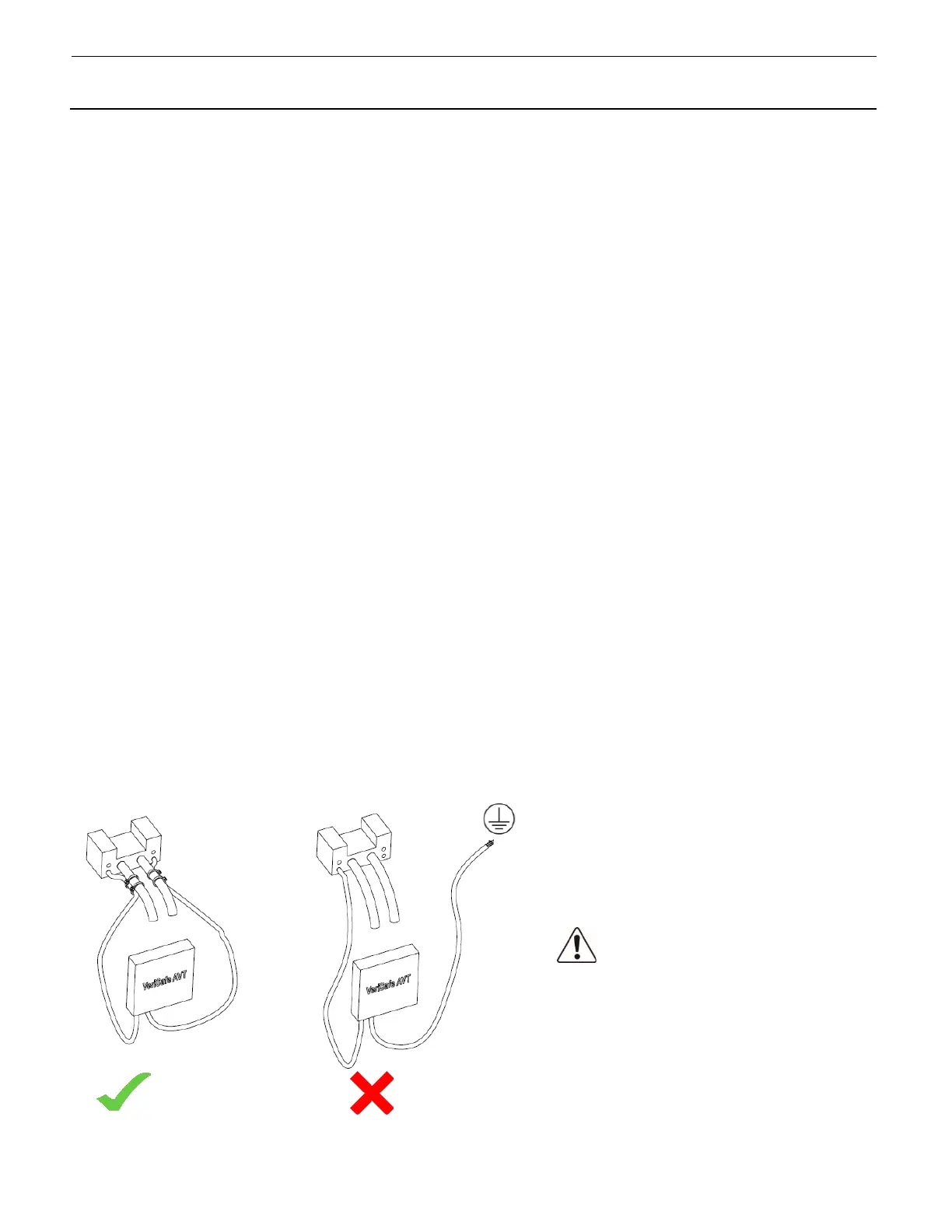
The VeriSafe AVT is designed with two Sensor Leads for each phase conductor. The two leads in each color set have different functions. The
Detection Lead is used to detect voltage and the Termination Lead is used to verify that the Detection Lead is in contact with a conductor.
The Termination Lead does not detect voltage. There are no labels distinguishing the Detection and Termination Leads because it is critical
that they are both properly terminated. If the Detection Lead is not contacting a conductor, the connectivity test will fail and prevent the
AVT from returning a Green Absence of Voltage indication.
The connectivity test is performed by measuring the discharge time of a capacitor inside the Isolation Module that is electrically connected
to the detection lead. If the Detection Lead is electrically connected to the Termination Lead, the discharge time will be inside the desired
range and the test will pass. If the Detection Lead is not in contact with a conductor, the discharge time will be outside of the desired range
and the test will fail. If the connectivity test fails on any Detection Lead, the green absence of voltage indicator on the AVT will not illuminate.
IMPORTANT: If the detection lead is not properly terminated to a power conductor and comes in contact with a low impedance path to
ground, the discharge time could be inside the desired range and the connectivity test would pass. This would be a multi-fault scenario,
but is possible if terminations are not made properly and secured. An AVT installed on a single-phase system might only have one Detection
Lead terminated to a power conductor. If the Detection Lead were to become loose and make contact with a low impedance path to ground,
the connectivity test would pass. However, voltage would not be detected because the termination lead does not detect voltage and the
Detection Lead is no longer in contact with the power conductor. This could result in a green absence of voltage indication, even though
the power conductor is energized. This would be less likely to occur with split-phase or three-phase systems as all Detection Lead
terminations would need to fail and each detection lead would have to make contact with a low impedance path to ground at the time of
the test. However, even the loss of a single detection lead termination on a multi-phase system could result in the scenario described above,
if voltage was only present on a single phase.
Utilization of the commissioning test described in this Instruction Manual will verify proper functionality of the AVT at the time of installation.
The failure modes described in this section would be the result of Sensor Lead terminations not being maintained over time and Sensor Leads
not being secured to the power conductors at time of installation. This likelihood of this scenario can be reduced by securing the Sensor
Leads to the power conductor or another nearby rigid feature to prevent movement in the event that the termination point failed. Sensor
Leads can be secured using cable ties, clamps, mounts or tape. The sensor leads should be secured at multiple locations, including near the
termination point. Additionally, the Schematics section of this Instruction Manual provides redundant detection schematics for both single-
phase and DC installations to provide a redundant Detection Lead on the power conductor.
Warning:
Secure Sensor Leads to prevent
accidental contact with ground.
 Loading...