© Panduit Corp. 2018
INSTRUCTION MANUAL VeriSafe AVT
B21075_00 Page: 13 of 20 04-2018
Installation Instructions
Warning:
• The AVT must be installed correctly and grounded as described in this Instruction Manual to provide proper indication of absence
of voltage. Sensor leads must not be mechanically connected with each other for the device to verify connection to the circuit.
Correct function of the device must be verified after installation (see commissioning checklist).
• Sensor leads of the same color should be terminated on the same conductor. Each conductor should have at least one sensor
lead set, as shown on the schematic diagrams.
• Excess length from Sensor Leads should be trimmed; lead wires should not be extended with a splice.
• Always comply with local installation codes and standards.
• Always follow safety and lockout/tagout procedures when working on or near electrical systems and equipment.
• If a Sensor Lead separates from the termination point to the power conductor and contacts a low impedance path to ground,
the connectivity test can be defeated resulting in a false absence of voltage indication. Ensure that all sensor leads are
terminated properly and secured to the power conductor or other nearby rigid feature to prevent movement if the termination
fails to remain intact.
• Devices must be installed in an enclosure where the internal compartment is only accessible by the use of a tool or other
mechanical means.
Before installation, verify that after power is removed from the
circuit to be monitored, the potential measured between each line and ground
V.
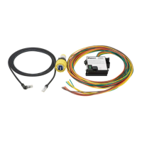
1. Insert the Indicator Module in the
30mm knockout hole, align anti-
rotation notch. Ensure the rubber
washer is on the outside of the
enclosure.
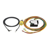
2. Install the panel nut with the flange
towards the inside surface of the
enclosure.
3. Tighten the panel nut until both it and the
sealing washer make full contact with the
enclosure surface. Then, tighten an
additional ¼ turn. Tighten the panel nut
with fingers only, do not overtighten.
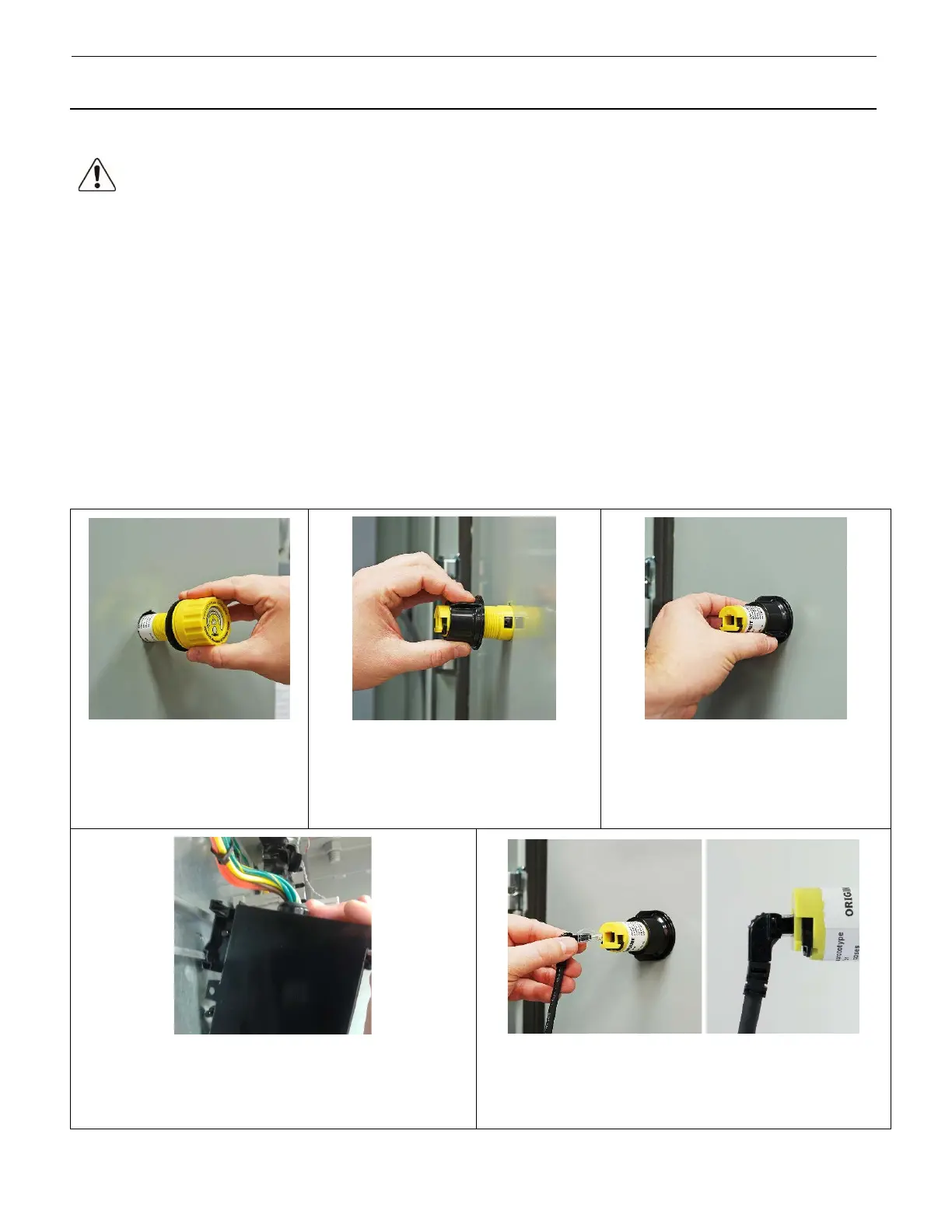
4. Snap the Isolation Module on the DIN rail. Alternately, the
Isolation Module can be mounted to any surface using three,
#8 pan head screws or another compatible fastener. Surface
mounting with screws is recommended for high-vibration
5. Insert the end of the AVT System Cable with the right-angle
connector in the back of the Indicator Module. Press firmly into
the opening until you feel it latch. Pull back on the connector to
verify that it has properly latched.
 Loading...