© Panduit Corp. 2018
INSTRUCTION MANUAL VeriSafe AVT
B21075_00 Page: 8 of 20 04-2018
Schematics
Warning:
• The AVT must be installed correctly and grounded as described in this Instruction Manual to provide proper indication of absence
of voltage. Sensor leads must not be mechanically connected with each other for the device to verify connection to the circuit.
Correct function of the device must be verified after installation (see commissioning checklist). Failure to comply with these
instructions could result in product failure, injury or death.
• Sensor leads of the same color should be terminated on the same conductor. Each conductor should have at least one sensor
lead set, as shown on the schematic diagrams.
• If a Sensor Lead separates from the termination point to the power conductor and contacts a low impedance path to ground,
the connectivity test can be defeated resulting in a false absence of voltage indication. Ensure that all sensor leads are
terminated properly and secured to the power conductor or other nearby rigid feature to prevent movement if the termination
fails to remain intact.
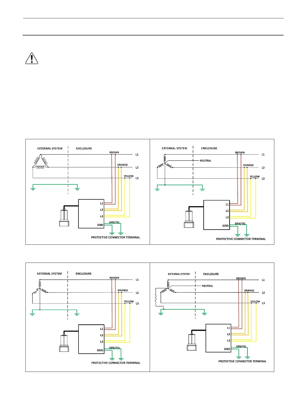
Three-Phase Delta: 3 Wire + PE Three-Phase WYE: 3 Wire + Neutral and PE
Three-Phase WYE: 3 Wire + PE (No Neutral) Three-Phase WYE High Resistance Ground: 3 Wire +
Neutral and PE

 Loading...