© Panduit Corp. 2018
INSTRUCTION MANUAL VeriSafe AVT
B21075_00 Page: 4 of 20 04-2018
Components
VeriSafe Indicator Module Faceplate Color
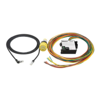
Note: The images shown in this manual are of the VeriSafe AVT model VS-AVT-C08-L10
The components of the Panduit VeriSafe Absence of Voltage Tester (AVT)
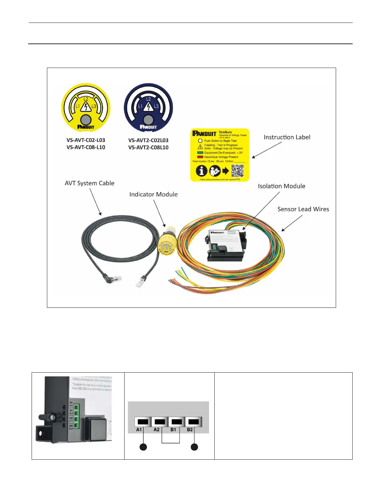
Output Contacts
The AVT includes a set of redundant dry contact signal outputs for optional use with control systems. These contacts are located on the Isolation
Module. The outputs are normally open and close only when the green Absence of Voltage Indicator is illuminated. By wiring to these contacts,
the AVT can be used as an input to a control system as well as log when the absence of voltage was verified.
Recommended Wiring
For redundant monitoring of output
state
Output Contact Specifications
• Two channel, single-pole, normally open
• Relay closure upon absence of voltage verification
• 5000 Vrms Input/Output Isolation
• Contacts rated for 30 V AC/DC
• Load Current 80 mA AC rms / mA DC
• On-Resistance 30 Ω (max)
• Compatible with up to 16 AWG (1 mm
2
)
• SIL3 compliant
• Duty Cycle: 10 seconds per test cycle
 Loading...