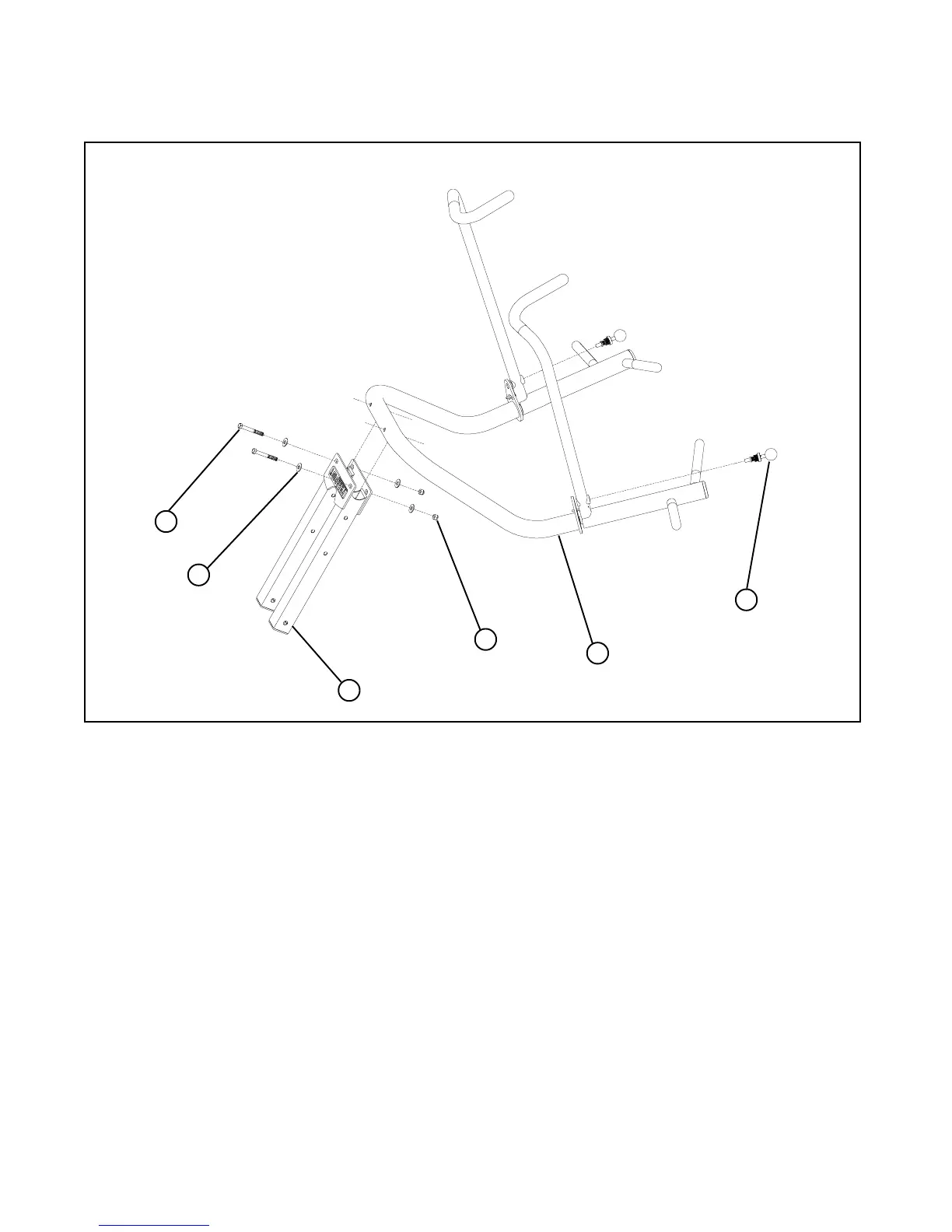
FIGURE 8
8
49
29
36
9
34
STEP 8:
• Place PRESS ARM (8) into PRIMARY PIVOT (9) and securely tighten using two 3/8 X 3” BOLTS (29), four 3/8” FLAT
WASHERS (36) two 3/8” LOCK NUTS (34)
• Insert and tighten two 3/8” LOCKING SPRING PINS (49) into PRESS HANDLES (6), (7).
3/8 X 3”
10
• Lock PRESS ARMS (6), (7) into place using 3/8” LOCKING SPRING PINS (49)
Locking
Spring Pin
• To disengage LOCKING SPRING PINS (49), pull out and twist 1/4 turn.