22
FIGURE 21
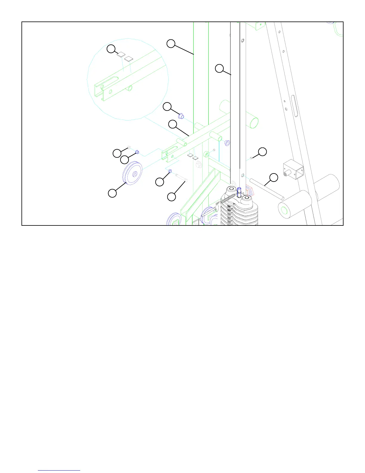
STEP 21
• Insert two 3/4” FLANGE BEARINGS (76) into the COUNTER LEVER (3) as shown in FIGURE 21.
• Hold the COUNTER LEVER (3) between the REAR (4) and MIDDLE UPRIGHTS (8) and slide the 3/4 DIA X 11” SHAFT (107) throught
the MIDDLE UPRIGHT (8), COUNTER LEVER (3), and through the collar on the REAR UPRIGHT (4). To SECURE the SHAFT (107) in
place, insert two 5/16” SET SCREWS (48) into the collars on the UPRIGHTS and tighten. See FIGURE 21.
• SECURELY attach one 4-1/2” PULLEY(43) to the COUNTER LEVER (3) using one 3/8 X 2-3/4” BOLT (85), two 3/8” FLANGE SPACERS
(49) and one 3/8” LOCK NUT (92). See FIGURE 21.
• SECURELY attach two 1 X 1” GLIDES (53) to the UNDERSIDE of the COUNTER LEVER (3) as shown in FIGURE 20.
53
4
8
76
107
3/8 X 2-3/4” 85
48
92
49
49
3
43
UNDERSIDE