25
0
1
2
345
6
1/2 1/2 1/2 1/2 1/2 1/2
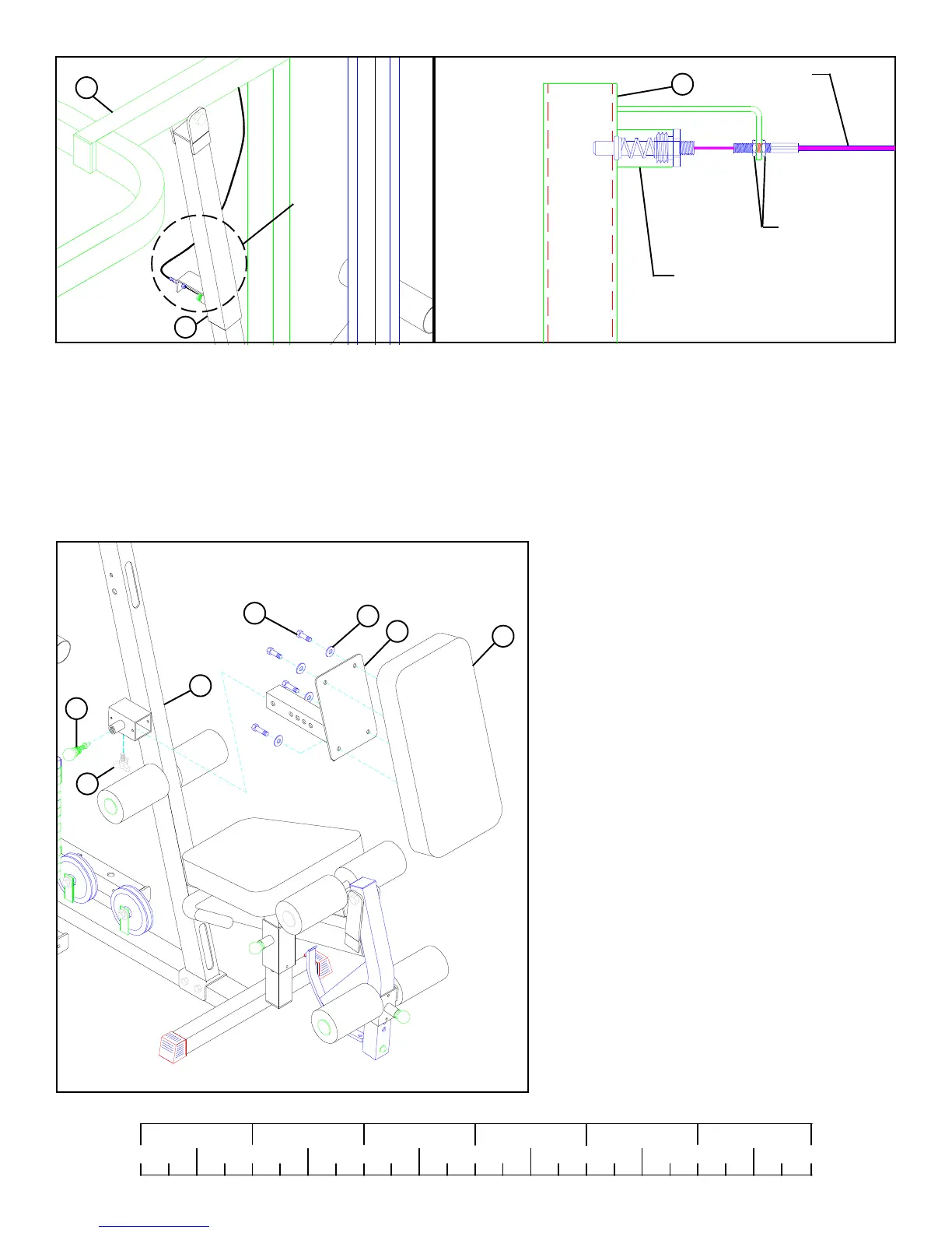
STEP 23
• SECURELY assemble the SPRING PIN ASSEMBLY of the PUSH/PULL CABLE to the SPRING PIN BARREL on the RECEIV-
ING TUBE (13). (!!! IMPORTANT !!! TIGHTEN THE NUT OF THE SPRING PIN ASSEMBLY SECURELY)
• Swing the PRESS ARM (27) up until the SPRING PIN of the PUSH/PULL CABLE engages in one of the adjustment holes.
• Thread the second 1/4-28 IN. NUT onto the threaded end of the CABLE, and cinch the two 1/4-28 IN. NUTS around the flat. (IMPOR-
TANT! DO NOT OVER TIGHTEN NUTS!)
• Use the extra thread on the end of the CABLE to adjust out slack. ( !!! DO NOT ADJUST OUT TO FAR !!! ALWAYS ALLOW
SPRING PIN ASSEMBLY TO FULLY ENGAGE)
FIGURE 25
DETAIL 25
DETAIL
23
1/4” NUTS
PUSH/PULL
CABLE
SPRING PIN
ASSEMBLY
13
DO NOT OVERTIGHTEN!
13
27
STEP 26
• SECURELY assemble the SEAT PAD (40) to the
BACK PAD ADJUST (16) using four 3/8 X 1-1/4”
BOLTS (83) and four 3/8” WASHERS (91). See
FIGURE 26.
FIGURE 26
• SECURELY assemble one 3/8” SPRING PIN ASSEM-
BLY (51) to the FRONT UPRIGHT (25) as shown in
FIGURE 26.
• Insert the SEAT PAD (40) & BACK PAD ADJUST
(16) into the FRONT UPRIGHT (25) while pulling back
on the SPRING PIN ASSEMBLY (51) until it engages
in one of the adjustment holes. See FIGURE 26.
3/8 X 1-1/4” 83
16
91
40
51
25
• Attach one 3-PRONG KNOB (61) the FRONT UPRIGHT
(25) as shown in FIGURE 26.
61