6
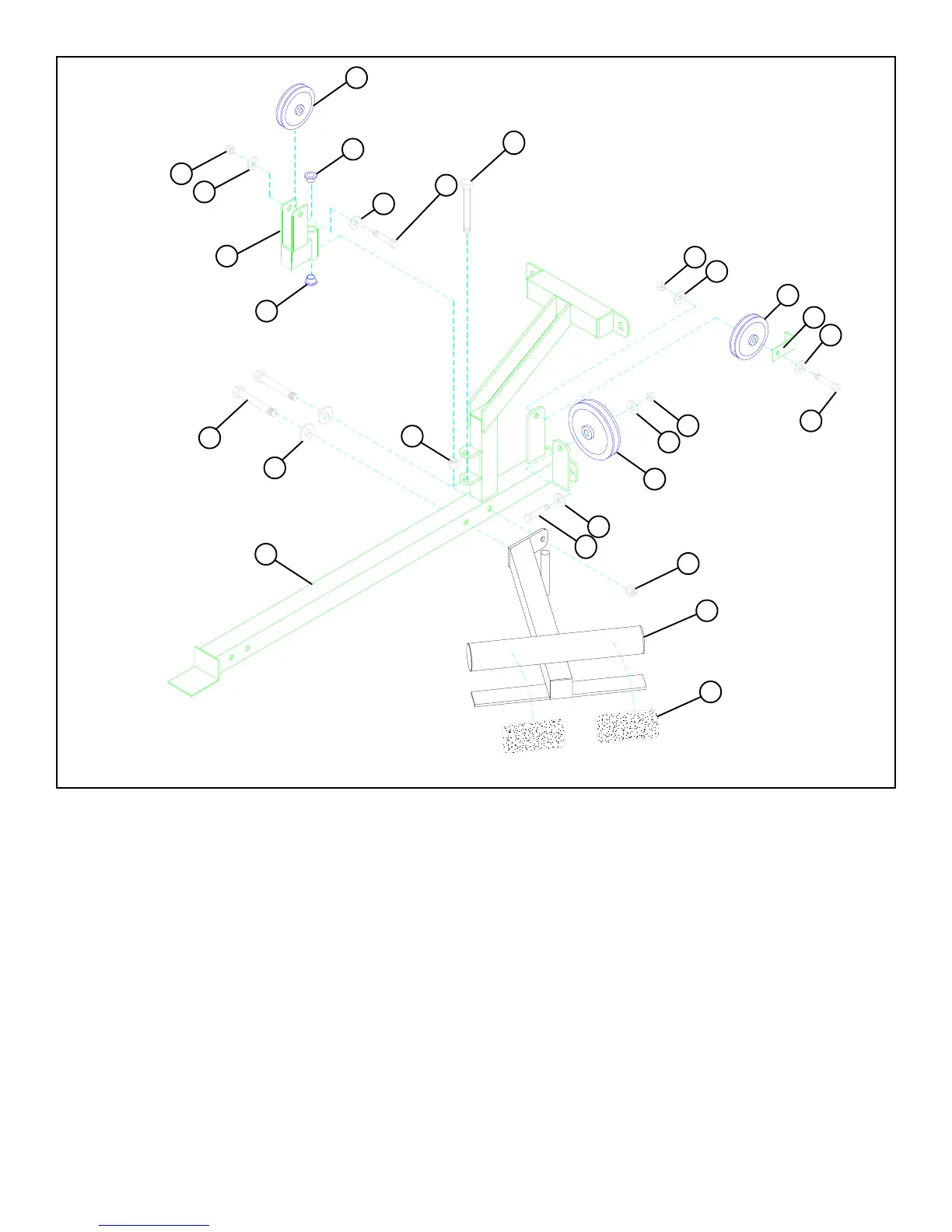
FIGURE 1
STEP 1
• SECURELY assemble the LOW ROW/CALF RAISE (2) to the PRESS BASE (18) using two 1/2 X 3" BOLTS (87), two 1/2"
WASHERS (93), and one 1/2" LOCK NUT (94).
• Insert two 1/2" FLANGE BEARINGS (78) into the SWIVEL PULLEY BRACKET (30) as in FIGURE 1.
• Assemble the SWIVEL PULLEY BRACKET (30) to the PRESS BASE (18) using one 1/2 X 3-1/2" BOLT (90) and one 1/2” LOW
HEIGHT LOCK NUT (95). (TIGHTEN THE CONNECTION ENOUGH TO REMOVE THE PLAY, YET ALLOWING THE
SWIVEL BRACKET TO ROTATE FREELY.)
• SECURELY assemble one 3-1/2” PULLEY (42) to the SWIVEL PULLEY BRACKET (30) using one 3/8 X 2" BOLT (84), two 3/
8” WASHERS (91), and one 3/8” LOCK NUT (92). See FIGURE 1.
• SECURELY assemble one 3-1/2" PULLEY (42) to the rear horizontal flat of the PRESS BASE (18) using one 3/8 X 2" BOLT (84),
one 2-3/8" CABLE RETAINING CLIP (45), two 3/8" WASHERS (91), and one 3/8" LOCK NUT (92) as shown in FIGURE 1.
(NOTE: 2-3/8” CABLE RETAINING CLIP (45) should face as shown in FIGURE 1.)
• Attach two 5-1/2 X 2-1/2" NON SKID STRIPS (65) to the LOW ROW/CALF RAISE (2) approximately where shown in FIGURE 1.
• SECURELY assemble one 4-1/2" PULLEY (43) to the lower horizontal flat of the PRESS BASE (18) using one 3/8 X 2" BOLT
(84), two 3/8" WASHERS (91), and one 3/8" LOCK NUT (92) as shown in FIGURE 1. (NOTE: Make sure there is no contact
between the two pulleys.)
91
92
30
78
42
92
78
91
93
43
95
42
45
91
91
18
2
94
92
65
90 1/2 X 3-1/2”
84 3/8 X 2”
1/2 X 3” 87
3/8 X 2” 84
3/8 X 2” 84
LOW HT.
91
91