30
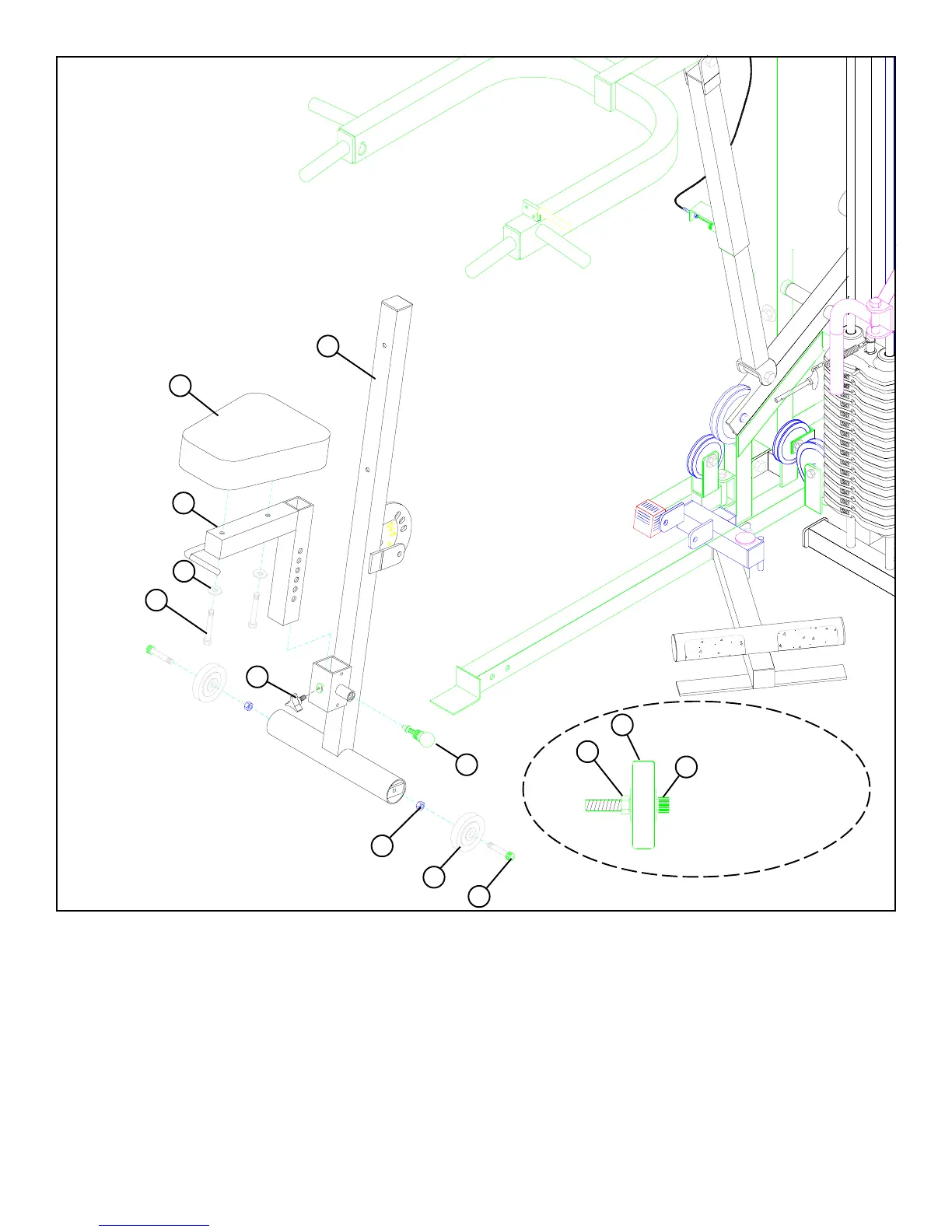
STEP 32
• SECURELY assemble one 3/8” SPRING PIN (51) to the spring pin housing of the PRESS BACK SUPPORT (23). (NOTE: Tighten
the nut of the SPRING PIN ASSEMBLY SECURELY.)
• SECURELY assemble two 3” WHEELS (63) using two BLACK 3/8 X 2-1/2” SOCKET HEAD CAP SCREWS (64) and two 3/8” HEX NUTS
(108) as shown in DETAIL 32.
• SECURELY assemble the SEAT PAD (38) to the PRESS SEAT ADJUST (12) using two 3/8 X 2-3/4” BOLTS (85) and two 3/8” WASHERS
(91). See FIGURE 32.
• Pull back the 3/8” SPRING PIN (51) on the PRESS BACK SUPPORT (23) and slide the PRESS SEAT ADJUST (12) into the
receiving well. Engage the 3/8” SPRING PIN (51) into one of the adjustment holes.
FIGURE 32
23
38
51
91
12
3/8 X 2-3/4” 85
3/8” HEX NUT 108
• SECURELY assemble two wheel assemblies to the PRESS BACK SUPPORT (23) as shown in FIGURE 32.
64 3/8 X 2-1/2” SOCKET HEAD CAP SCREW
64 3/8 X 2-1/2” SOCKET
HEAD CAP SCREW
63
108
63
DETAIL 32
61
• Assemble one 3-PRONG KNOB (61) the PRESS BACK SUPPORT (23) as shown in FIGURE 32.