31
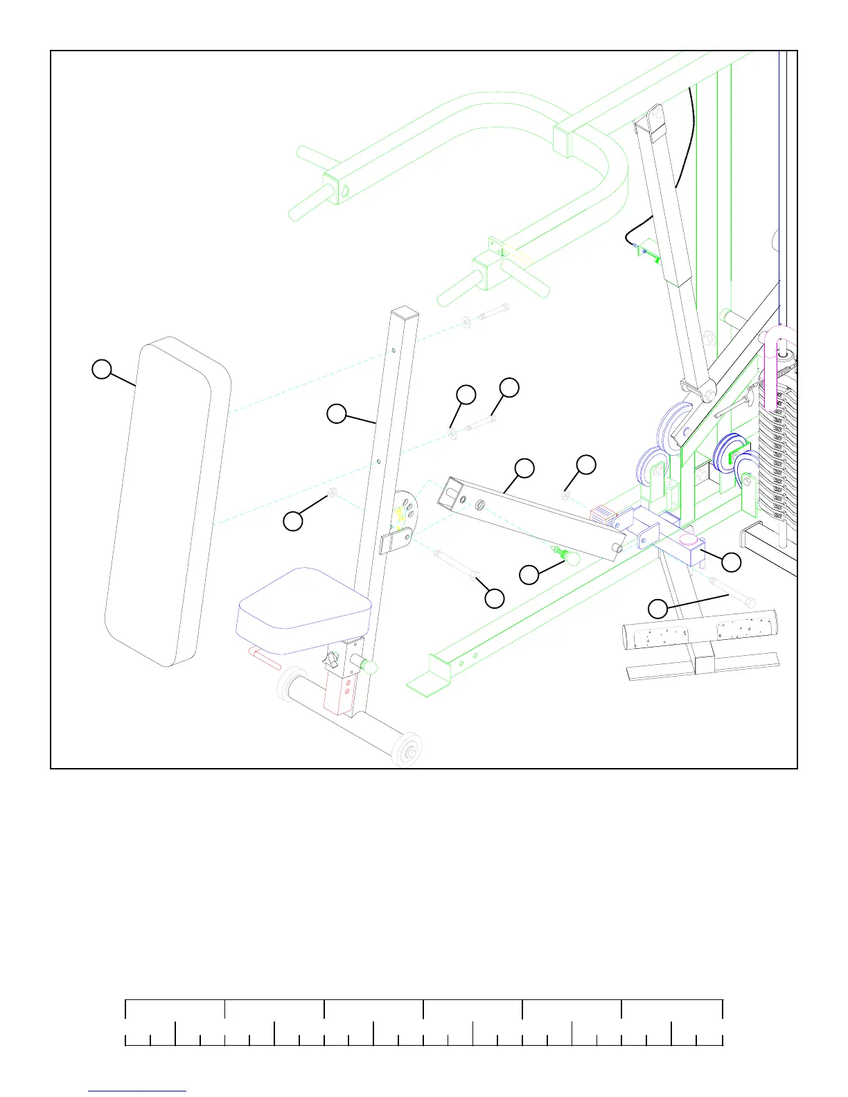
FIGURE 33
STEP 33
0
1
2
345
6
1/2 1/2 1/2 1/2 1/2 1/2
• SECURELY assemble one 1/2” SPRING PIN ASSEMBLY (52) to the spring pin housing on the PRESS SUPPORT TUBE (21).
(NOTE: Tighten the nut of the SPRING PIN ASSEMBLY SECURELY.)
• SECURELY assemble the BACK PAD (39) to the PRESS BACK SUPPORT (23) using two 3/8 X 2-3/4” BOLTS (85) and two 3/8”
WASHERS (91). See FIGURE 33.
85 3/8 X 2-3/4”
95 LOW
HEIGHT
52
23
91
39
21
95 LOW
HEIGHT
10
1/2 X 4-1/2” 89
1/2 X 3” 87
• SECURELY assemble the PRESS BACK SUPPORT (23) to the PRESS SUPPORT TUBE (21) using one 1/2” X 3” BOLT (87)
and one 1/2” LOW HEIGHT LOCK NUT (95). (NOTE: Tighten the connection enough to remove play, yet allowing the
PRESS BACK SUPPORT to rotate freely).
• SECURELY assemble the PRESS SUPPORT TUBE (21) to the PRESS SWIVEL (10) using one 1/2” X 4-1/2” BOLT (89) and
one 1/2” LOW HEIGHT LOCK NUT (95). (NOTE: Tighten the connection enough to remove play, yet allowing the PRESS
SUPPORT TUBE to rotate freely).
 Loading...


