24
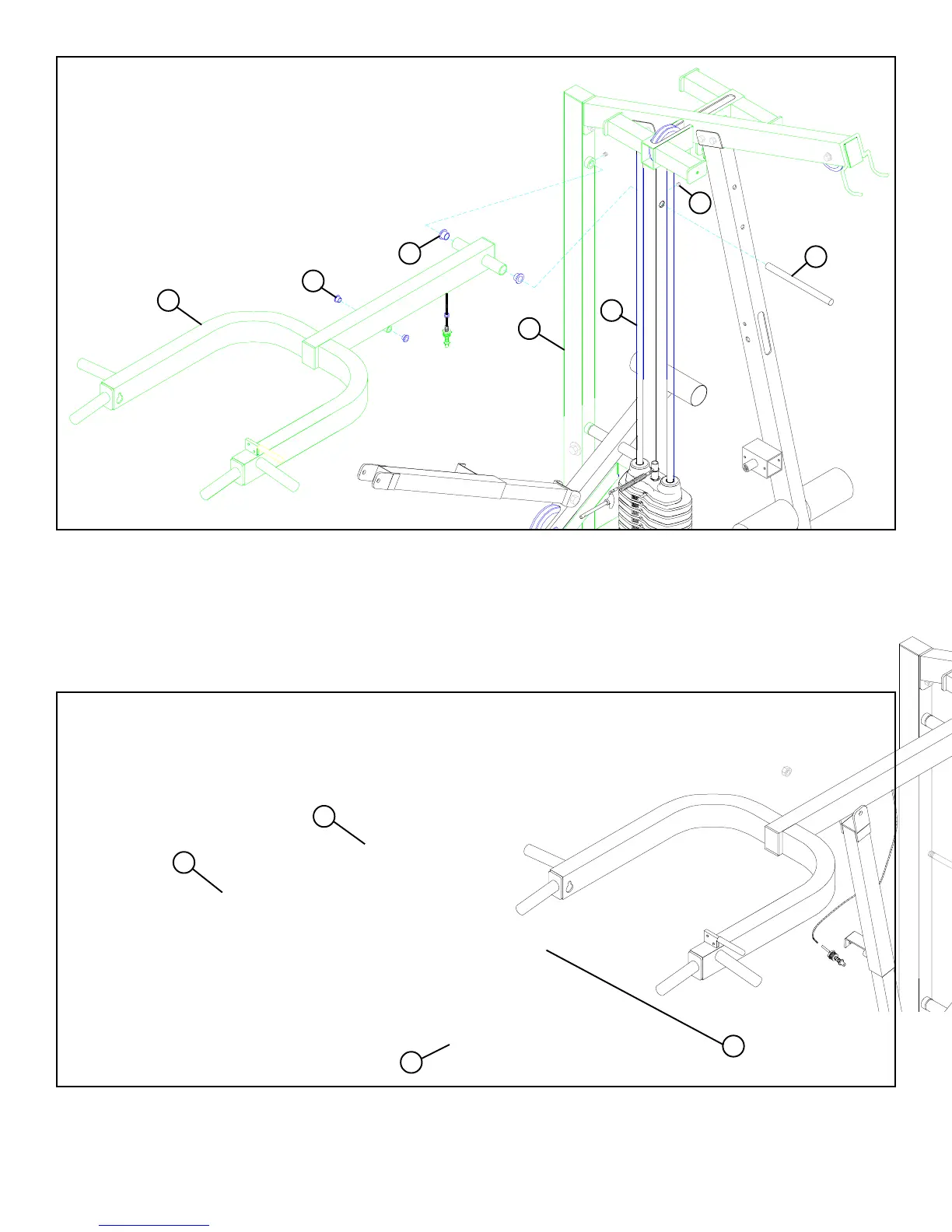
FIGURE 23
STEP 23
• Insert two 3/4” FLANGE BEARINGS (76) into the PRESS ARM (27) as shown in FIGURE 23.
• Hold the PRESS ARM (27) between the REAR (4) and MIDDLE UPRIGHTS (8) and slide the 3/4 DIA X 11” SHAFT (107) throught
the MIDDLE UPRIGHT (8), PRESS ARM (27), and through the collar on the REAR UPRIGHT (4). To SECURE the SHAFT (107) in
place, insert two 5/16” SET SCREWS (48) into the collars on the UPRIGHTS and tighten. See FIGURE 23.
• Insert two 1/2” FLANGE BEARINGS (78) into the PRESS ARM (27) as shown in FIGURE 23.
STEP 24
FIGURE 24
• Assemble the RECEIVING TUBE (13) to the PRESS ARM (27) using one 1/2 X 3” BOLT (87) and one 1/2” LOW HEIGHT LOCK NUT
(95). (NOTE: Tighten the connection enough to remove play, yet allowing the PRESS ARM (2) to rotate freely.) See FIGURE 24.
48
107
76
4
8
27
78
95 LOW HEIGHT NUT
27
13
87 1/2 X 3”