27
FIGURE 28
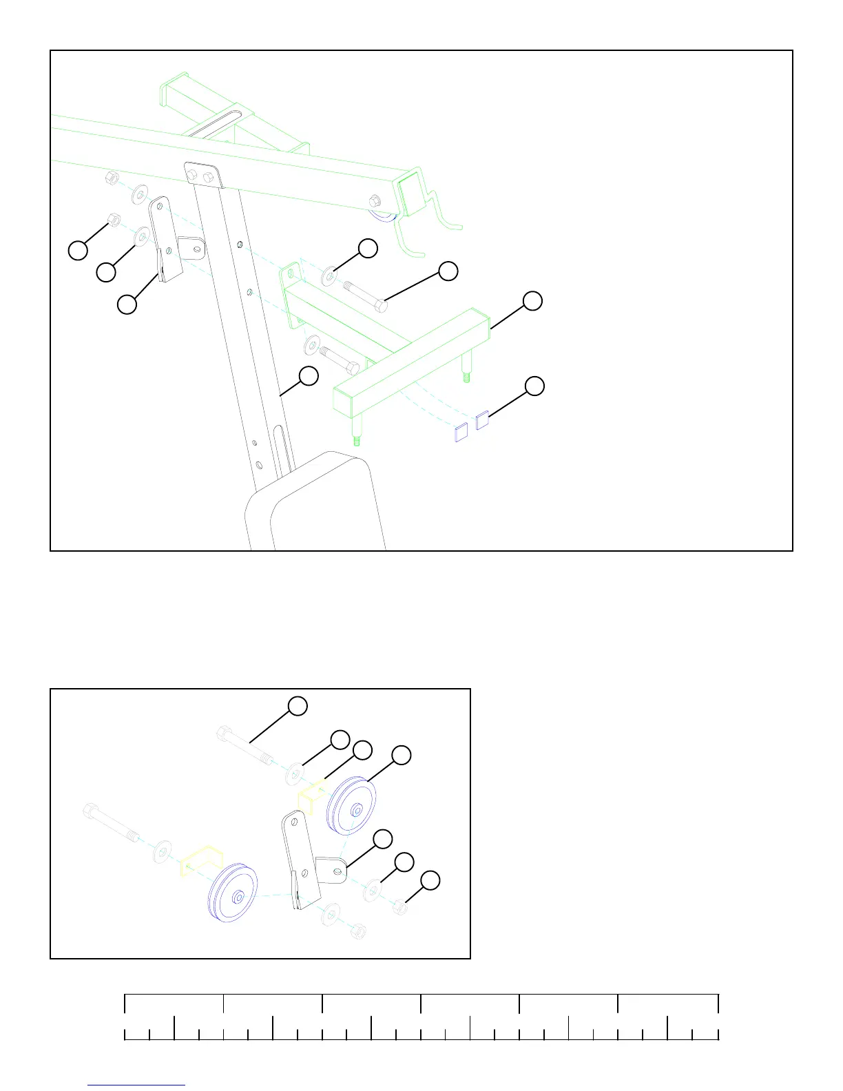
STEP 28
0
1
2
345
6
1/2 1/2 1/2 1/2 1/2 1/2
FIGURE 29
STEP 29
• LOOSELY assemble two 3-1/2” PULLEYS (42) to the
CENTER PULLEY BRACKET (26) using two 3/8 X 2”
BOLTS (84), two 2-3/8” L-BRACKETS (45), four 3/8”
WASHERS (91), and two 3/8” LOCK NUTS (92). See
FIGURE 29.
(NOTE: This connection wil be tightened after the
cable has been routed.)
• SECURELY assemble the BEARING HOUSING (6) and the CENTER PULLEY BRACKET (26) to the FRONT UPRIGHT (25) using two
1/2 X 4-1/2” BOLTS (89) , four 1/2” WASHERS (93), and two 1/2" LOCK NUTS (94). See FIGURE 28.
• Attach two 1 X 1" GUIDES (53) to the ANGLE on the UNDERSIDE of the BEARING HOUSING (6). See FIGURE 28.
94
91
93
26
93
53
25
6
91
92
42
45
26
89 1/2 X 4-1/2”
84 3/8 X 2”