1 2 3
4
6
7
9
12
10
17
15
16
5
8
13
11
14
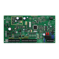
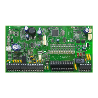
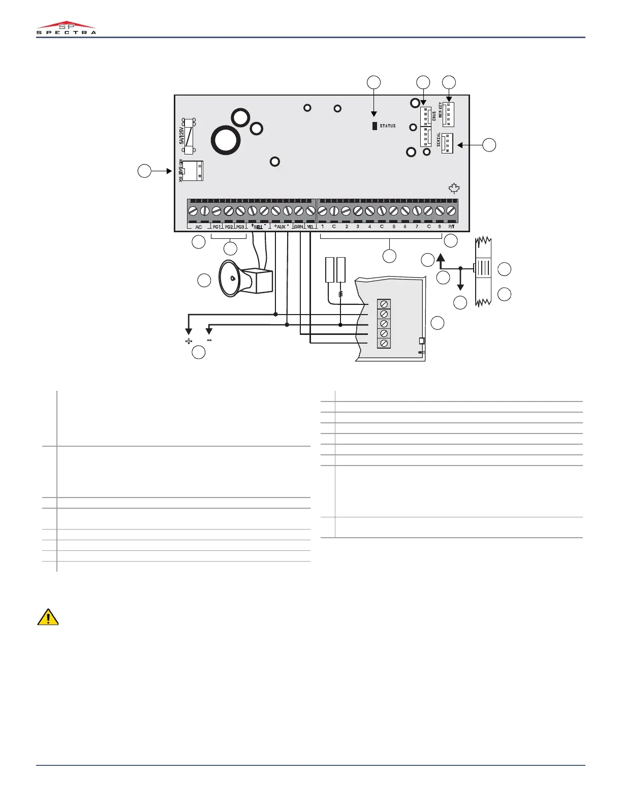
1 Status LED:
• Flash once every second: Normal
• Flashes ON 1 sec. and OFF 1 sec.: Any trouble
• Always ON: Panel is using phone line
Fast flash 6 seconds after power-up: Installer lock enabled
2
EBUS port used for GSM reporting using the PCS Series GSM
Communicator Module; if using a CVT485 Plug-In RS485 Converter,
connect the PCS module to the RS485 bus;
DIALER and EBUS port used for voice reporting with the VDMP3 Plug-in
Voice Module.
3Paradox Memory Key (PMC-4, PMC5)
4 Used for connecting the IP Internet Module; also used for In-Field
Firmware upgrade through a 307USB Direct Connect Interface
5 Panic/tamper input
6 Refer to Hardware Connections on page 58
7The
BELL output will shutdown if the current exceeds 3A
8 Refer to Alarm Relay and PGM Connections on page 59
9 16.5 Vac (50 or 60 Hz), minimum 20 VA (40 VA recommended)
10 Refer to AC Power & Backup Battery Connections on page 59
11 Connect to any common input
12 AWG #14 single conductor solid copper wire
13 Ground clamp
14 Cold water pipe grounding
15 To metallic enclosure
16 To connect additional wiring to auxiliary power, use the red (+) and black
(-) keypad connectors; auxiliary power will shut down if current exceeds
1.1A; if the auxiliary output is overloaded and shuts down, you must
disconnect all loads from the output for at least 10 sec. before
reconnecting any load back to the auxiliary output
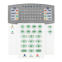
17 For the keypad’s zone configurations, see Installer Quick Menu on page 7;
If EOL is enabled, see section [706] option 2, on page 38
Panel Reset
To perform a panel reset, see Panel Reset on page 3.
40 VA transformer strongly recommended.
Max. number of keypads: 15 keypads
Max. aux. current: 500 mA
Max. distance of bus module from panel: 76 m (250 ft.)
Max. total run of wire: 230 m (750 ft.)
This equipment must be installed and maintained by qualified service personnel only.
For UL and C-UL warnings, refer to the UL and C-UL Warnings section at the back of the MGSP Reference & Installation Manual.
The sum of the current drawn from the
BELL and AUX must be limited to 1.3A. Exceeding this limit will overload the panel power supply
and lead to complete system shutdown.
 Loading...