Page 92 · Robotics with the Boe-Bot
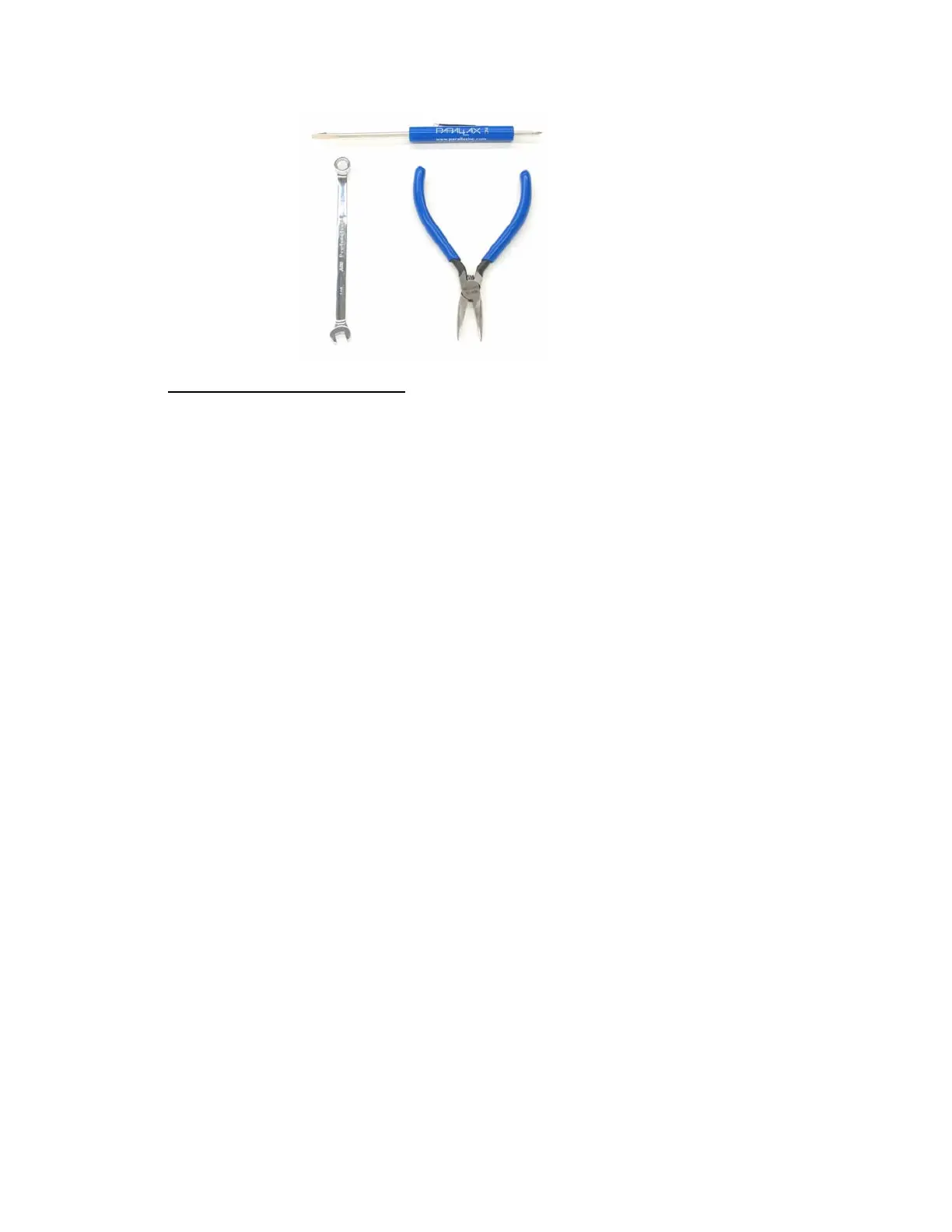
Figure 3-1
Boe-Bot
Assembly
Tools
Mounting the Topside Hardware
√ Start by gathering this list of parts.
√ Then, follow the accompanying instructions.
Parts List:
See Figure 3-2.
(1) Boe-Bot chassis
(4) 1″ Standoffs
(4) Pan head screws, 1/4″ 4-40
(1) Rubber grommet, 13/32″
Instructions:
√ Insert the 13/32″ rubber grommet into the
hole in the center of the Boe-Bot chassis.
√ Make sure the groove in the outer edge of
the rubber grommet is seated on the edge of
the hole in the chassis.
√ Use the four 1/4″ 4-40 screws to attach the
four standoffs to the chassis as shown.