Chapter 2: Your Boe-Bot’s Servo Motors · Page 41
Chapter 2: Your Boe-Bot’s Servo Motors
This chapter will guide you through connecting, adjusting, and testing the Boe-Bot’s
motors. In order to do that, you will need to understand certain PBASIC commands and
programming techniques that will control the direction, speed, and duration of servo
motions. Therefore, Activities #1, #2, and #5 will introduce you to these programming
tools, and then Activities #3, #4, and #6 will show you how to apply them to the servos.
Since precise servo control is key to the Boe-Bot’s performance, completing these
activities before mounting the servos into the Boe-Bot chassis is both important and
necessary!
INTRODUCING THE CONTINUOUS ROTATION SERVO
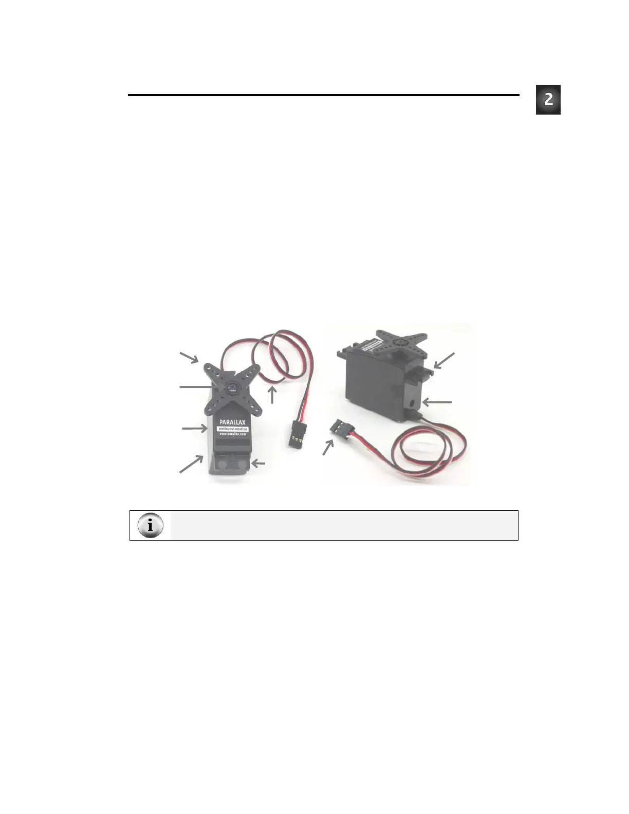
The Parallax Continuous Rotation servos shown in Figure 2-1 are the motors that will
make the Boe-Bot’s wheels turn. This figure points out the servos’ external parts. Many
of these parts will be referred to as you go through the instructions in this and the next
chapter.
Figure 2-1
Parallax Continuous Rotation Servo
TIP: You may find it useful to bookmark this page so that you can refer back to it later.
Cable
for
power
and
control
signal
Access hole
for center
adjusting
feedback
potentiometer
Control
horn
Phillips
screw
Mounting
Flange
Mounting
Flange
Label should
read
“Continuous
Rotation”
Case contains
motor, circuits,
and gears
Plug for RC servo
connection ports on
Board of Education