Page 174 · Robotics with the Boe-Bot
ACTIVITY #2: FIELD TESTING THE WHISKERS
Assume that you may have to test the whiskers at some later time away from a computer.
Since the Debug Terminal won’t be available, what can you do? One solution would be
to program the BASIC Stamp so that it sends an output signal that corresponds to the
input signal it’s receiving. This can be done with a pair of LED circuits and a program
that turns the LEDs on and off based on the whisker inputs.
Parts List:
(2) Resistors - 220 Ω (red-red-brown)
(2) LEDs – Red
Building the LED Whisker Testing Circuits
√ Disconnect power from your board and servos.
√ If you have a Board of Education, add the circuit shown in Figure 5-9 with the
help of the wiring diagram in Figure 5-10 (page 175).
√ If you have a HomeWork Board, add the circuit shown in Figure 5-9 with the
help of the wiring diagram in Figure 5-11 (page 176).
P1
P10
Vss
Vss
LEDLED
220
Ω
220
Ω
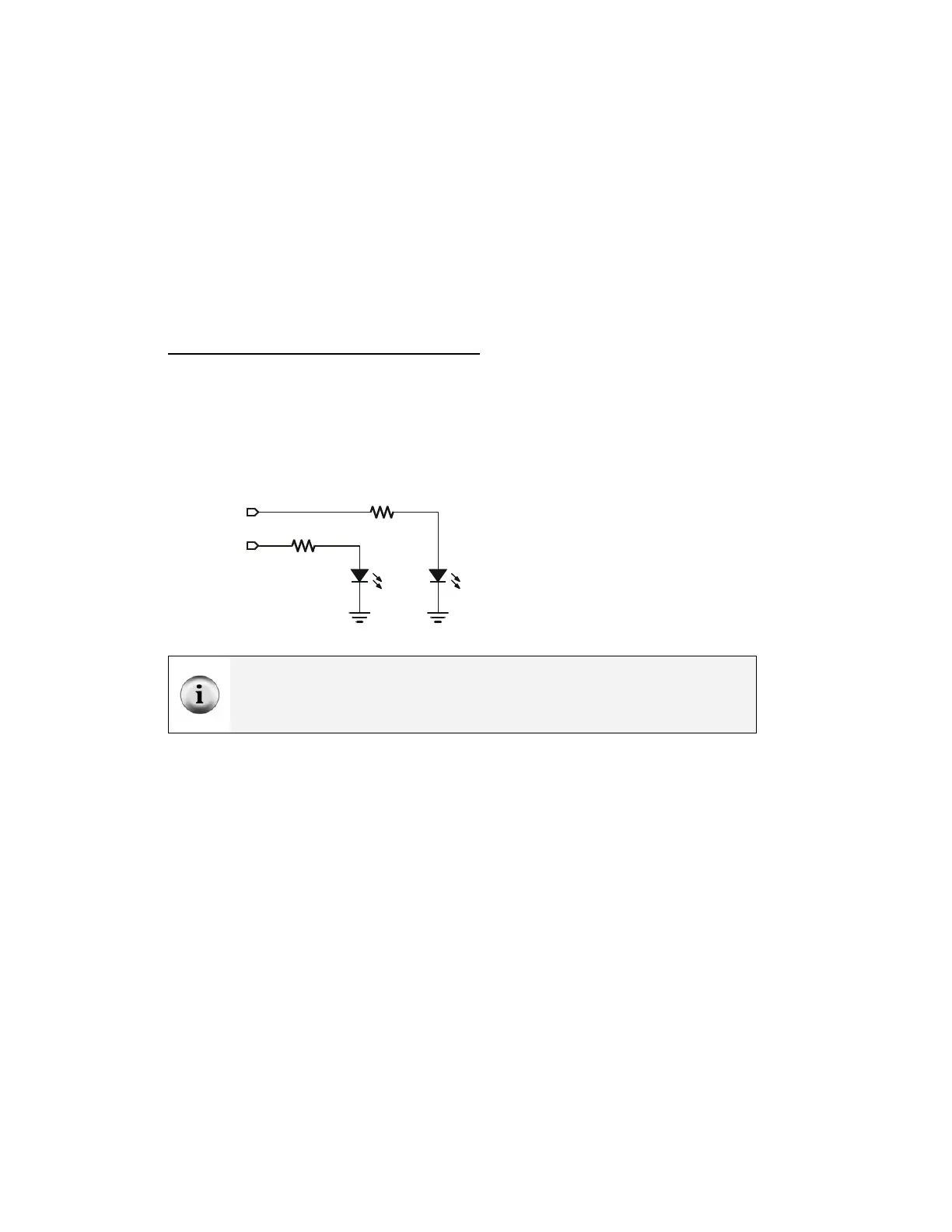
Figure 5-9
LED Whisker
Testing
Schematic
Add this LED
circuit.
Remember that an LED is a one way current valve. If it is plugged in backwards, it will
not let current pass through, and so will not emit light. For the LED to emit light when the
BASIC Stamp sends a high signal, the LED's anode must be connected to the 220 Ω
resistor, and its cathode must be connected to Vss. See Figure 5-10 or Figure 5-11.