Chapter 6: Light Sensitive Navigation with Photoresistors · Page 197
Vdd
Vss
2 k
Ω
Vo
R
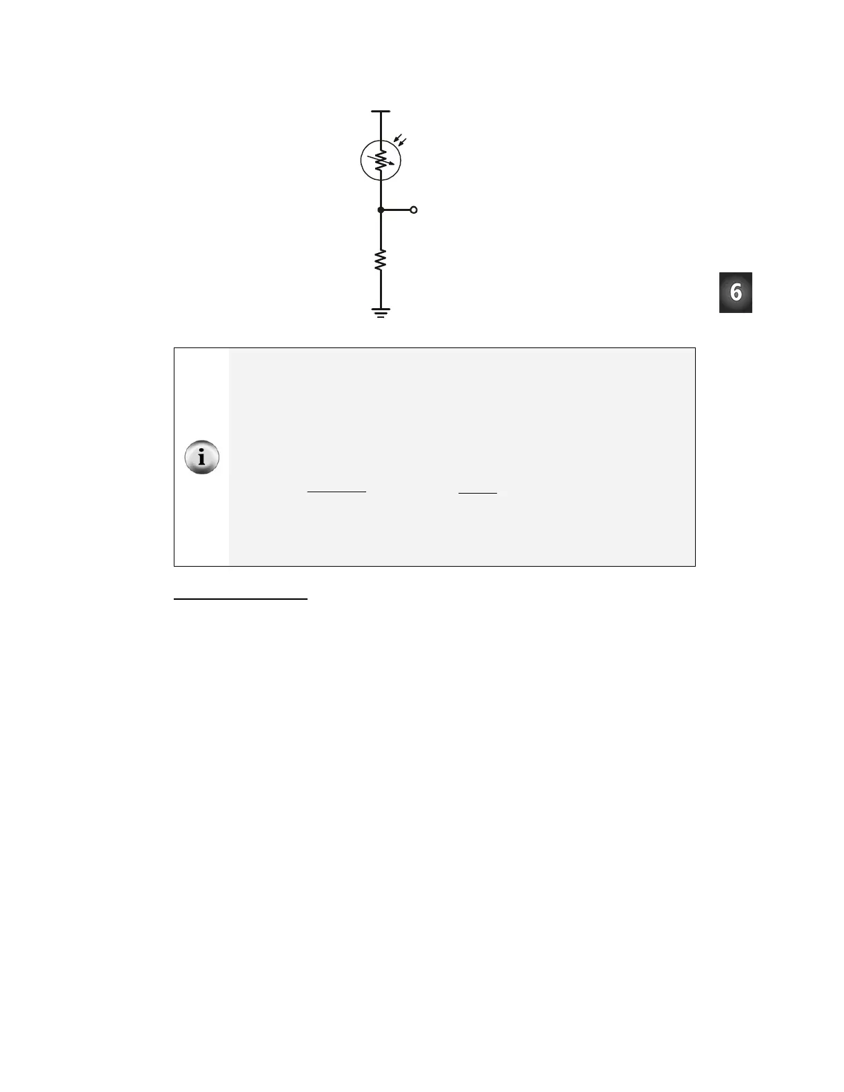
Figure 6-4
Schematic –
Voltage Divider
Circuit
When resistors are connected end-to-end as shown in Figure 6-4 they are connected in
series, and they can be referred to as series resistors.
When two resistors are connected in series to set a voltage at Vo, the circuit is called a
voltage divider. In this circuit, the value of Vo can be anywhere between Vdd and Vss.
The exact value of Vo is determined by the ratio of R to 2 kΩ. When R is larger than 2 kΩ,
Vo will be closer to Vss. When R is smaller than 2 kΩ, Vo will be closer to Vdd. When R is
equal to 2 kΩ, Vo will be 2.5 V. If you measure one of the two values (R or Vo), you can
calculate the other value using one of these two equations.
R0002
0002
V5Vo
+Ω
Ω
×=
Ω−
⎟
⎠
⎞
⎜
⎝
⎛
Ω
×= 2000
Vo
2000
V5R
1.4 V is called the BASIC Stamp I/O pin’s threshold voltage, also known as the I/O pin’s
logic threshold. When voltage sensed by an I/O pin is above that threshold, the I/O pin’s
input register will store a 1. If it is below that value, the I/O pin’s input register will store a 0.
Detecting Shadows
Casting a shadow makes the photoresistor’s resistance value (R) larger, which in turn
makes Vo smaller. The 2 kΩ resistors were chosen to make the value of Vo reside
slightly above the BASIC Stamp I/O pin’s 1.4 V threshold in a well lit room. When you
cast a shadow over it with your hand, it should send Vo below the 1.4 V threshold.
In a well lit room, both
IN6 and IN3 will store the value 1. If you cast a shadow over the
photoresistor divider connected to P6, it will then store a 0. Likewise, if you cast a
shadow over the photoresistor divider connected to P3, it will cause
IN3 to store a 0.