Page 238 · Robotics with the Boe-Bot
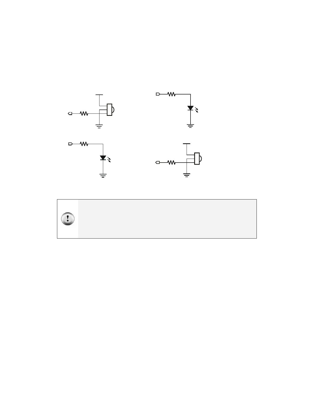
One IR pair (IR LED and detector) is mounted on each corner of the breadboard. Figure
7-4 shows the IR headlights circuit as a schematic and Figure 7-5 shows the circuit as a
wiring diagram.
√ Disconnect power from your board and servos.
√ Build the circuit shown by the schematic in Figure 7-4, using the wiring diagram
for your board in Figure 7-5 as a reference for parts placement.
Figure 7-4
Left and Right IR
Pairs
Left IR Pair Right IR Pair
Watch your IR LED anodes and cathodes!
Remember that the anode lead is the longer lead on an IR LED by convention, but that you
need to check the LED’s plastic case to make sure. The cathode lead is the one near the
flat spot on the case. In Figure 7-5, the anode lead of each IR LED connects to a 1 kΩ
resistor. The cathode lead plugs into the same breadboard row as an IR detector’s center
pin, and that row connects to Vss with a jumper wire.
Vdd
Vss
P9
P8
IR
LED
Vss
1 k
Ω
220
Ω
Vdd
Vss
P0
P2
IR
LED
Vss
1 k
Ω
220
Ω