Page 316 · Robotics with the Boe-Bot
P15
P14
P13
P12
P11
P10
P9
P8
P7
P5
P4
P3
P2
P1
P0
P6
X2
X3
Vdd VssVin
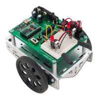
Figure D-7
Resistor, Photoresistor,
and Capacitor Wiring
Diagram
Keep in mind that the wiring diagrams presented here as solutions to the schematics are
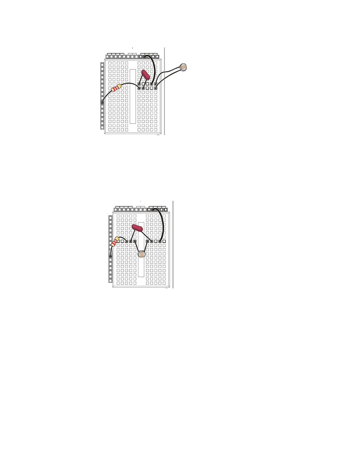
not the ONLY solutions to those schematics. For example, Figure D-8 shows another
solution to the schematic just discussed. Follow the connections and convince yourself
that it does satisfy the schematic.
P15
P14
P13
P12
P11
P10
P9
P8
P7
P5
P4
P3
P2
P1
P0
P6
X2
X3
Vdd VssVin
Figure D-8
Resistor, Photoresistor, and
Capacitor Wiring Diagram
Note the alternative parts
placement.