Page 46 · Robotics with the Boe-Bot
This resistance value is called the ohm, and the sign for the ohm is the Greek letter omega
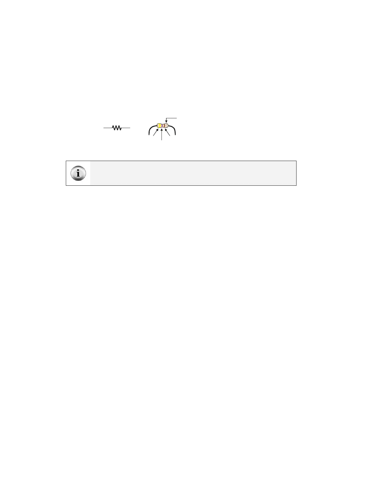
- Ω. The resistor you will be working with in this activity is the 470 Ω resistor shown in
Figure 2-2. The resistor has two wires (called leads and pronounced “leeds”), one
coming out of each end. There is a ceramic case between the two leads, and it’s the part
that resists current flow. Most circuit diagrams that show resistors use the symbol on the
left with the squiggly lines to tell the person building the circuit that he or she must use a
470 Ω resistor. This is called a schematic symbol. The drawing on the right is a part
drawing used in some beginner level Stamps in Class texts to help you build circuits.
470
Ω
Yell ow
Violet
Brown
Gold
Silver
or
Blank
Figure 2-2
470 Ω Resistor Part
Drawing
Schematic symbol (left)
and part drawing (right)
The colored stripes indicate resistance values. See Appendix C: Resistor Color Codes
for information on how to determine a resistor's value from the colored stripes on its ceramic
case.
A diode is a one-way current valve, and a light emitting diode (LED) emits light when
current passes through it. Unlike the color codes on a resistor, the color of the LED
usually just tells you what color it will glow when current passes through it. The
important markings on an LED are contained in its shape. Since an LED is a one-way
current valve, you have to make sure to connect it the right way, or it won’t work as
intended.
Figure 2-3 shows an LED’s schematic symbol and part drawing. An LED has two
terminals. One is called the anode, and the other is called the cathode. In this activity,
you will have to build the LED into a circuit, and you will have to pay attention and make
sure the anode and cathode leads are connected to the circuit properly. On the part
drawing, the anode lead is labeled with the plus-sign (+). On the schematic symbol, the
anode is the wide part of the triangle. In this part drawing, the cathode lead is the pin
labeled with a minus-sign (-), and on the schematic symbol, the cathode is the line across
the point of the triangle.