Page 48 · Robotics with the Boe-Bot
LED Test Circuits
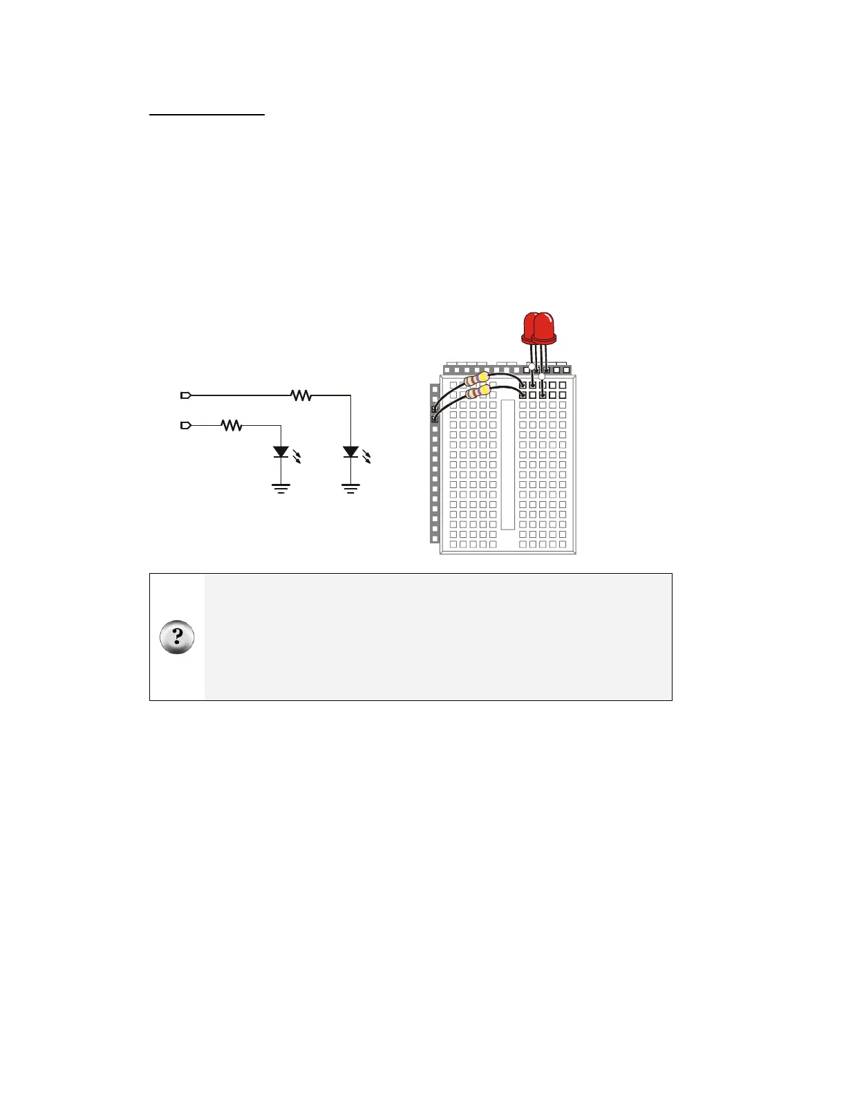
If you completed the What’s a Microcontroller? text, you are no doubt very familiar
with the circuit shown in Figure 2-4. The left side of this figure shows the circuit
schematic, and the right side shows a wiring diagram example of the circuit built on your
board’s prototyping area.
√ Build the circuit shown in Figure 2-4.
√ Make sure that the shorter pins on each LED (the cathodes) are plugged into
black sockets labeled Vss.
√ Make sure the longer pins (the anodes, marked with a ⊕ in the wiring diagram)
are connected to the white breadboard sockets exactly as shown.
P12
P13
Vss
Vss
LEDLED
470
Ω
470
Ω
P15
P14
P11
P10
P9
P8
P7
P6
P5
P4
P3
P2
P1
P0
P13
P12
X2
X3
Vdd VssVin
+
+
Figure 2-4
Two LEDs
Connected
to BASIC
Stamp I/O
Pins P13
and P12
Schematic
(left) and
wiring
diagram
(right).
What's an I/O pin? I/O stands for input/output. The BASIC Stamp has 24 pins, 16 of which
are I/O pins. In this text, you will program the BASIC Stamp to use I/O pins as outputs to
make LED lights turn on/off, control the speed and direction the Parallax Continuous
Rotation servos turn, make tones with speakers, and prepare sensors to detect light and
objects. You will also program the BASIC Stamp to use I/O pins as inputs to monitor
sensors that indicate mechanical contact, light level, objects in the Boe-Bot's path, and even
their distance.
New to building circuits? See Appendix D: Breadboarding Rules.
 Loading...