Chapter 2: Your Boe-Bot’s Servo Motors · Page 67
turning. You will then use a screwdriver to adjust them so that they stay still. This is
called centering the servos. After the adjustment, you will test the servos to make sure
they are functioning properly. The test programs will send signals that make the servos
turn clockwise and counterclockwise at various speeds.
Servo Tools and Parts
The Parallax screwdriver shown in Figure 2-21 is the only extra tool you will need for
this activity. Alternately, any Phillips #1 point screwdriver with a 1/8″ (3.18 mm) shaft
should do the trick.
Figure 2-21
Parallax
Screwdriver
Sending the Center Signal
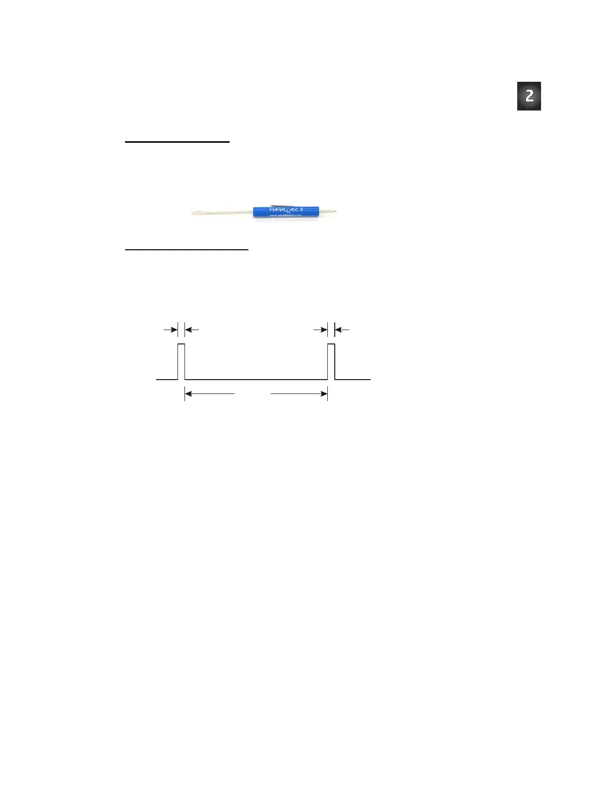
Figure 2-22 shows the signal that has to be sent to the servo connected to P12 to calibrate
it. This is called the center signal, and after the servo has been properly adjusted, this
signal instructs it to stay still. The instruction consists of a series of 1.5 ms pulses with 20
ms pauses between each pulse.
P12
1.5 ms
1.5 ms
20 ms
Figure 2-22
Timing Diagram for
CenterServoP12.bs2
The 1.5 ms pulses
instruct the servo to
remain still.
The program for this signal will be a PULSOUT command and a PAUSE command inside a
DO…LOOP. Figuring out the PAUSE command from the timing diagram is easy, it's going to
be
PAUSE 20 for the 20 ms between pulses.
Figuring out the
PULSOUT command's Pin argument isn't that hard either, it's going to be
12, for I/O pin P12. Next, let's figure out what the
PULSOUT command's Duration
argument has to be for 1.5 ms pulses. 1.5 ms is 1.5 thousandths of a second, or 0.0015 s.
Remember whatever number is in the
PULSOUT command's Duration argument, multiply
that number by 2 µs (2 millionths of a second = 0.000002 s), and you will know how long