isysNet 24 VDC Analog Output Modules, Series A (PSSTACM12A, PSSTAVM12A) E111P
3
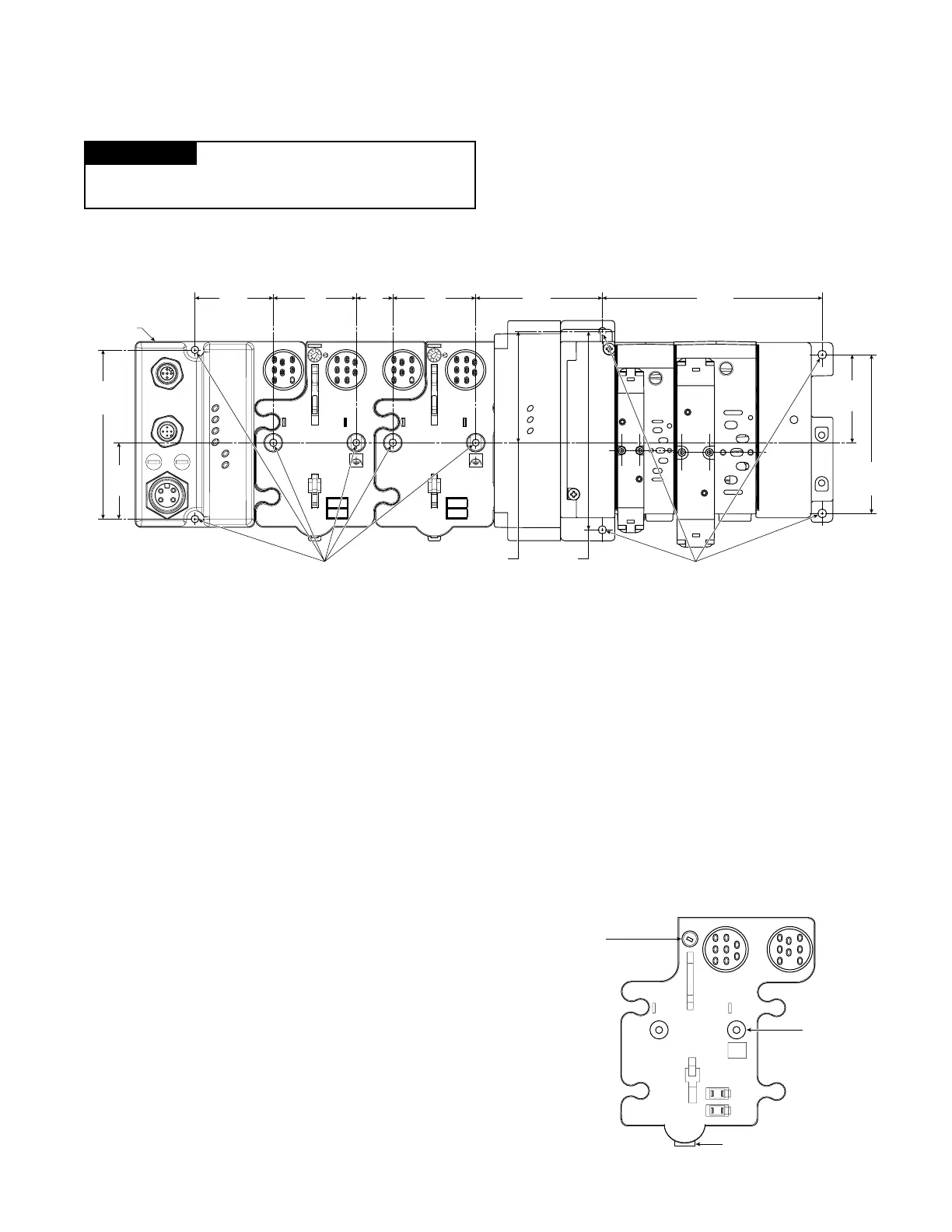
Inches
(mm)
Adapter
2.0
(50)
2.0
(50)
1.9
(47.2)
4.02
(102)
1.81
(46)
4.32
(109.8)
5.39
(137.0)
Drill and Tap
for M4 Screw
2.39
(60.7)
3.02
(76.6)
3.13
(79.4)
5.98*
(151.9)
0.87
(22)
Drill and Tap
for M6 Screw
Ground Lug
Connection
Latching Mechanism
Mounting Base
Keyswitch-
Set to position 4
for the analog
output
modules
Install the Mounting Base as Follows:
1. Lay out the required points as shown above in the drilling
dimension drawing.
2. Drill the necessary holes for #8 (M4) machine or self-tapping
screws.
3. Mount the base using #8 (M4) screws.
4. Ground the system using the ground lug connection. (The ground
lug connection is also a mounting hole.)
Mount the I/O Base
To mount the I/O base on a wall or panel, use the screw holes
provided in the base.
IMPORTANT
The I/O module must be mounted on a grounded metal mounting
plate or other conductive surface.
A mounting illustration for the base with an adapter is shown below.
* Depending on the type and number of manifolds, this dimension
may vary. Refer to Catalog 0600P-# for additional information.
 Loading...


