isysNet 24 VDC Analog Output Modules, Series A (PSSTACM12A, PSSTAVM12A) E111P
5
Wire the Analog Output Modules
Following are wiring instructions for the analog output modules.
Make sure all connectors and caps are securely tightened to
properly seal the connections against leaks and maintain IP67
requirements.
ATTENTION
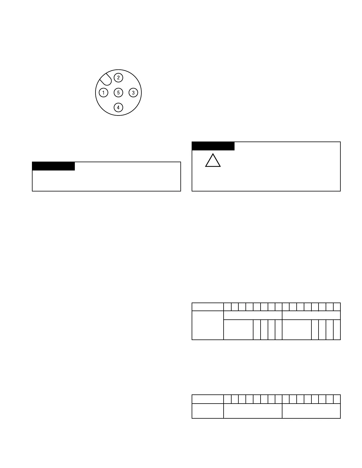
(view into connector)
Pin 1 - Output 0 (M12-A)
Output 1 (M12-B)
Pin 2 - 24VDC
Pin 3 - Common
Pin 4 - Common
Pin 5 - No Connect
PSSTACM12A and PSSTAVM12A
IMPORTANT
Analog modules have ear th grounded metal rings.
This should be considered when choosing shielded cables and
grounding techniques.
Communicate With Your Module
I
/O messages are sent to (consumed) and received from (produced)
the I/O modules. These messages are mapped into the processor’s
memory. These I/O analog output modules produce 2 bytes of input
data (scanner Rx - fault status). They consume 4 bytes of output
data (scanner Tx).
Default Data Map for the Analog Output Modules
PSSTACM12A and PSSTAVM12A
Message Size: 2 Bytes
15 14 13 12 11 10 09 08 07 06 05 04 03 02 01 00
Produces
High Byte-Channel 1 Status Low Byte-Channel 0 Status
(Scanner Rx)
Not H L C C Not H L C C
Used C C M F Used C C M F
A A A A
Where: CF = Channel Fault Status, 0 = no error, 1 = fault
CM = Calibration Mode; 0 = normal, 1 = calibration mode
LCA = Low Clamp Alarm; 0 = no error, 1 = fault
HCA = High Clamp Alarm; 0 = no error, 1 = fault
PSSTACM12A and PSSTAVM12A
Message Size: 4 Bytes
15 14 13 12 11 10 09 08 07 06 05 04 03 02 01 00
Consumes
Output Channel 0 High Byte Output Channel 0 Low Byte
(scanner Tx)
Output Channel 1 High Byte Output Channel 1 Low Byte
EDS File Requirements
The EDS files are available online at www.parker.com/pneu/isysnet.
 Loading...


