isysNet 24 VDC Analog Output Modules, Series A (PSSTACM12A, PSSTAVM12A) E111P
4
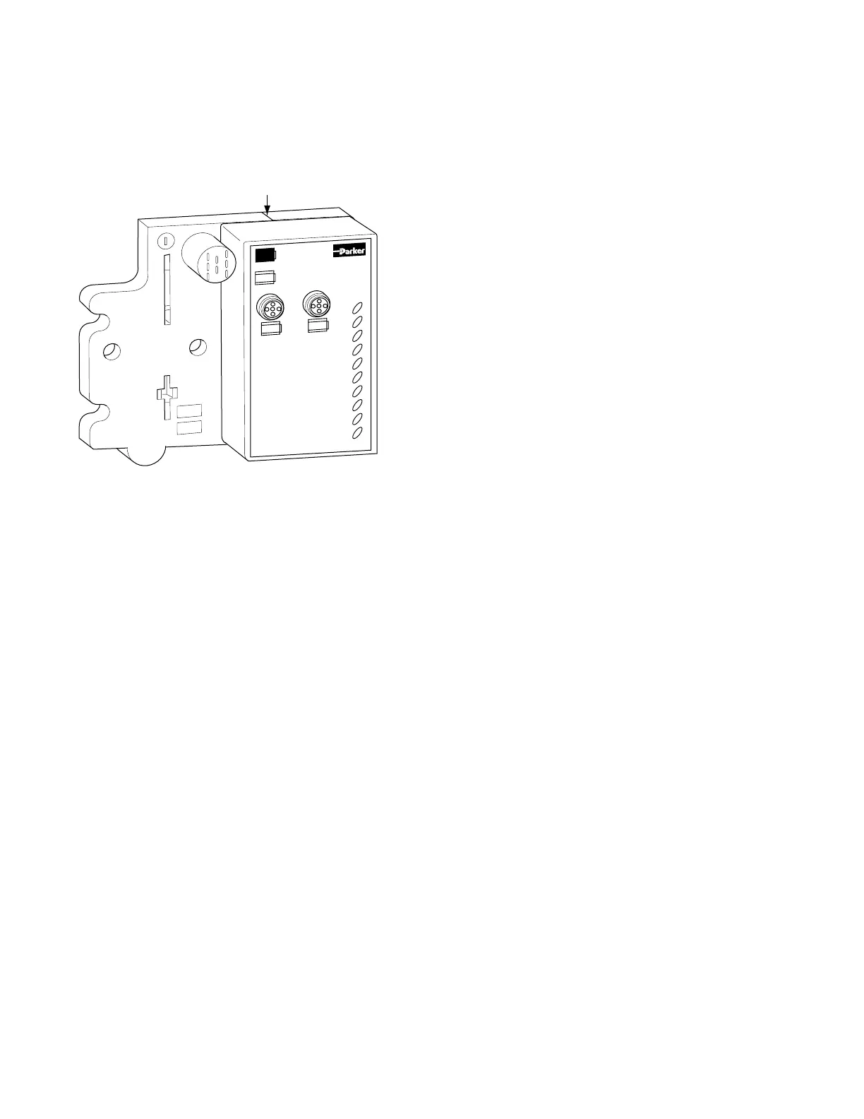
Install the Analog Output Module
To Install the Analog Output Module, Proceed as Follows:
1.
Using a bladed screwdriver, rotate the keyswitch on the mounting
base clockwise until the number 4 aligns with the notch in the
base.
2. Position the module vertically above the mounting base. The
module will bridge two bases.
3.
Push the module down until it engages the latching mechanism. You
will hear a clicking sound when the module is properly engaged.
The locking mechanism will lock the module to the base.
Remove the Analog Output Module From the
Mounting Base
To Remove the Module from the Mounting Base:
1. Put a flat blade screwdriver into the slot of the orange latching
mechanism.
2. Push the screwdriver toward the I/O module to disengage the
latch. The module will lift up off the base.
3. Pull the module off of the base.
MOD
NET
PSSTACM12A
Analog Curren
t Ou
t
0
1
0
1
Module Will Bridge Two Bases
 Loading...


