TECHNICAL SPECIFICATION
59
Medium Flow Compressed Air Dryers - IOMI.
0.680.710.730.760.790.820.850.890.941.001.141.331.592.002.634.00
Dryer Performance
DRYER MODEL
PRESSURE
DEWPOINT
STANDARD
ISO 85731:2010
WATER
CLASSIFICATION
PRESSURE
DEWPOINT
OPTIONAL
ISO 85731:2010
WATER
CLASSIFICATION
PRESSURE
DEWPOINT
OPTIONAL
ISO 85731:2010
WATER
CLASSIFICATION
o
C
o
F STANDARD
o
C
o
F OPTIONAL
o
C
o
F OPTIONAL
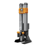
CDAS HL
-40 -40 Class 2.2.2 -70 -100 Class 2.1.2 -20 -4 Class 2.3.2
OFAS HL
-40 -40 Class 2.2.0 -70 -100 Class 2.1.0 -20 -4 Class 2.3.0
FBP HL
-40 -40 Class 1.2.0 -70 -100 Class 1.1.0
- - -
Important Note Regarding -70°C (-100°F) Dewpoint.
A compressed air dryer supplying a pressure dewpoint of -70°C (-100°F) requires a dierent desiccant ll to dryers supplying a
standard -40°C / - 20°C pressure dewpoint. During shipping, desiccant material adsorbs atmospheric moisture. Following installation,
commissioning and initial operation, the dryer will start to "dry down" until it provides the desired -70°C (-100°F). Once achieved, the
dryer will continue to supply air at the required dewpoint, however it is important to note that the dry down period may take several
days / weeks to achieve the -70°C (-100°F) dewpoint.
Technical Data
Flow Rates
DRYER MODEL
MIN OPERATING
PRESSURE
MAX OPERATING
PRESSURE
MIN OPERATING
TEMPERATURE
MAX OPERATING
TEMPERATURE
MAX AMBIENT
TEMPERATURE
BAR G PSI G BAR G PSI G
o
C
o
F
o
C
o
F
o
C
o
F
CDAS/OFAS/FBP HL
4 58 16 232 5 41 50 122 55 131
DRYER MODEL
Pipe Size
BSPP or NPT
INLET FLOW RATE
L/S M/MIN M/HR CFM
CDAS/OFAS/FBP HL 050
1/2” 15 0.92 55 32
CDAS/OFAS/FBP HL 055
1/2” 19 1.17 70 41
CDAS/OFAS/FBP HL 060
1/2” 25 1.50 90 53
CDAS/OFAS/FBP HL 065
1/2” 31 1.84 110 65
CDAS/OFAS/FBP HL 070
3/4” 42 2.51 150 88
CDAS/OFAS/FBP HL 075
1” 51 3.09 185 109
CDAS/OFAS/FBP HL 080
1” 61 3.67 220 129
CDAS/OFAS/FBP HL 085
1 1/2” 83 5.01 300 177
Stated ows are for operation at 7 bar g (100 psi g / 0.7 MPa g) with reference to 20ºC, 1 bar a, 0% relative water vapour pressure.
 Loading...