EasyManua.ls Logo

Parker Airtek TW 300 User Manual

Parker Airtek TW 300
53 pages
To Next Page IconTo Next Page
Page #1 background imageLoading...
Page #1 background image
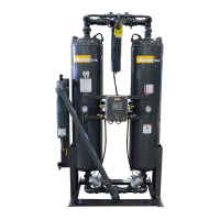
HEATLESS DESICCANT
COMPRESSED AIR DRYER
MODEL’S 75 - 6000
S/N
INSTALLATION, OPERATION
& MAINTENANCE MANUAL
Service Department
1-800-451-6023

Questions and Answers:

Parker Airtek TW 300 Specifications

General IconGeneral
BrandParker
ModelAirtek TW 300
CategoryDehumidifier
LanguageEnglish

Summary

Installation and Inspection

Inspection and Site Preparation

Inspect dryer upon arrival, check location requirements, and ensure clean, well-lighted, vibration-free area.

Installation Requirements and Connections

Covers installation notes, warnings, required connections like inlet/outlet piping, pre-filters, and auto drains.

Safety and System Precautions

General Safety Precautions

Use caution around dryer, relieve pressure before servicing, disconnect power, wear eye/ear protection.

Overpressure and Drain Safety

Safety relief valves protect equipment; ensure proper drainage of water, oil, and particulates.

Component Failure and Desiccant Handling

Preventive maintenance reduces component failures; handle desiccant (Activated Alumina) with care.

General Operation

Bed Cycling and Regeneration

Saturated inlet air cycles through two beds; one dries, the other regenerates using depressurized dry air.

Sequence of Operation

Dryer Operation Cycle Overview

Dryer removes water vapor; Joule-Thomson cooling may cause slight condensate at exhaust. Repressurization prevents bed fluidization.

Step 1: Left Drying, Right Regenerating

Describes solenoid states and valve actions for left tower drying and right tower regenerating.

Step 2: Left Drying, Right Repressurizing

Details solenoid and valve actions as the right tower repressurizes from atmospheric to line pressure.

Step 3: Left Regenerating, Right Drying

Details solenoid and valve actions for left tower regenerating and right tower drying.

Step 4: Left Repressurizing, Right Drying

Describes solenoid and valve actions for left tower repressurization and right tower drying.

Start Up

Pre-Start Checks and Preparation

Read manual, check wiring, ensure correct power, provide protection, and depressurize control air.

Initial Dryer Pressurization

Slowly open inlet/outlet isolation valves to pressurize dryer, preventing desiccant bed fluidization.

Bypass Valve and Muffler Operation

Close bypass valve tightly; start dryer without mufflers for initial dust removal (use hearing/eye protection).

Operational Notes

Servicing and Leak Checks

Never service without relieving pressure; check all air connections for leaks.

Shutdown Procedures

Isolation Steps

Steps to isolate the dryer: repressurize, remove power, open bypass, close outlet/inlet isolation valves.

Demand Cycles

Maintenance Program

Daily Checks

Check dew point/humidity, purge setting/flow, gauge readings, auto drain operation, and regenerating tower back pressure.

Desiccant Replacement

Spare Parts Lists

2000 CFM Spare Parts List

Trouble Shooting Guide

Dryer Not Operating

Troubleshooting steps for dryer not operating (no lights or no switching) due to blown fuse, power, controller, or mode settings.

Failure to Switch or Outlet Dewpoint Issues

Addresses issues like incorrect time delay, no cycling, wrong purge rate, exceeded capacity, or liquid water at inlet.

Moisture Downstream and Air Loss

Troubleshooting for excessive air loss on regenerating tower and moisture downstream issues.

Valve Leaks and Pressure Drop

Troubleshooting for leaking exhaust valves, excessive pressure drop due to filter/desiccant issues, and unit not fully repressurizing.

Control Air and Solenoid Issues

Addresses problems with inlet/exhaust valves not functioning, no control air, and bleed from control solenoid or vent.

Wiring Diagrams

High Humidity

Precautions and Hazards

Emphasizes caution with powered terminals and warns against improper testing that can damage the sensor.

Timing Charts

PowerLoc System

PowerLoc Quick-Start Guide

Steps for start-up of dryers with Powerloc, including probe connection and initial stabilization.

Powerloc Troubleshooting

Troubleshooting for blank display indicates a power line fault; check connections or consult factory.

Warranty

Warranty Procedure

Call factory for service; phone call helps diagnose, remedy, assess parts, and authorize service.

Related product manuals