EasyManua.ls Logo

Parker Airtek TW 10 - User Manual

Parker Airtek TW 10
53 pages
To Next Page IconTo Next Page
Loading...
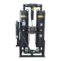
HEATLESS DESICCANT
COMPRESSED AIR DRYER
MODEL’S 75 - 6000
S/N
INSTALLATION, OPERATION
& MAINTENANCE MANUAL
Service Department
1-800-451-6023

Questions and Answers:

Parker Airtek TW 10 Specifications

General IconGeneral
BrandParker
ModelAirtek TW 10
CategoryDehumidifier
LanguageEnglish

Summary

Section 1 Installation and Inspection

Inspection

Factory testing, arrival inspection, and damage reporting procedures for the dryer.

Dryer Location

Guidelines for selecting an appropriate, accessible, and safe location for the dryer unit.

Installation Requirements

Essential connections, pre-filtration, and temperature considerations for proper dryer setup.

Recommended Installation Diagram

Visual guide illustrating minimum and ideal piping and component arrangements.

Section 2 Safety and System Precautions

General Safety Precautions

Essential safety measures for operating and servicing the dryer, including personal protective equipment.

System Component Safety

Warnings regarding component failures, desiccant dust handling, and safe disposal practices.

Section 3 General Operation

Principle of Adsorption

Explanation of how desiccant dryers remove water vapor using the adsorption process.

Desiccant Bed Operation

Overview of the two-bed system, drying, and regeneration cycles for the dryer.

Purge Air Consumption

Details on purge air usage and its impact on dryer efficiency and operating cost.

Section 4 Sequence of Operation

Operational Cycle Steps

Detailed breakdown of the dryer's operational cycle steps and solenoid valve functions.

Repressurization Procedure

Explanation of the repressurization phase before switching towers for proper operation.

Section 5 Start Up

Pre-Start Checks and Procedures

Important steps before energizing the dryer, including wiring and isolation valve checks.

Initial Operation and Settings

Procedures for powering up the dryer, initial cycle activation, and setting adjustments.

Section 7 Shutdown Procedures

Isolation and Depressurization

Steps to safely isolate the dryer, remove power, and release pressure before maintenance.

Section 8 Demand Cycles

Demand Cycle Overview

Introduction to Cycle Loc, Pro Purge, and Powerloc for improved dryer efficiency.

Cycle Loc and Pro Purge Functionality

How Cycle Loc and Pro Purge features operate for dew point monitoring and optimization.

Powerloc System Operation

Details on the Powerloc digital dew point monitor and its control capabilities.

Section 9 Maintenance Program

Daily, Weekly, and Semi-Annual Checks

Routine maintenance tasks including checks on drains, filters, and desiccant condition.

Annual Maintenance Tasks

Annual procedures such as valve inspection, solenoid cleaning, and probe recalibration.

Section 10 Parts (General Parts Description)

Desiccant Replacement

Procedures and quantities for replacing desiccant material in the dryer unit.

Valve Repair and Component Identification

Steps for repairing valves and descriptions of various dryer components.

Optional Equipment Parts

List of spare parts for optional features like Pro-Purge and Dewpoint Probes.

Section 11 Trouble Shooting Guide

Dryer Not Operating & Switching Failures

Troubleshooting steps for common issues when the dryer is not powered or not switching cycles.

Outlet Dewpoint and Moisture Issues

Diagnosing and resolving high dew point, moisture, and excessive air loss problems.

Valve and Control System Issues

Addressing issues with pressure drop, valves, control air, and solenoids for troubleshooting.

Section 12 Wiring Diagrams

Sequence Annunciator Wiring

Diagram illustrating the electrical connections for the sequence annunciator panel.

Dew Point Monitor Wiring

Wiring schematic for the dew point monitor and its associated probes and outputs.

Section 13 High Humidity

High Humidity Alarm Operation

How the High Humidity Alarm (HHA) system functions with a hygrosensor for control.

HHA Calibration and Precautions

Procedures for calibrating the HHA system and important safety precautions.

Section 14 Timing Charts

Load Cycle Timing Charts

Charts detailing solenoid and light states for 100% and short load cycles.

75% and 50% Load Cycle Timing

Timing charts illustrating solenoid and light states for 75% and 50% load cycles.

Section 15 Analyzing Chart

Operational Checks and Analysis

List of checks to perform during tower drying to assess system performance and diagnose issues.

Section 16 PowerLoc System

Powerloc Quick-Start and Theory

Initial setup steps and the design theory of the Powerloc microprocessor dew point analyzer.

Probe Installation and Analyzer Connection

Procedures for mounting the sensor probe and connecting it to the Powerloc analyzer.

Powerloc Display and Settings

Information on the Powerloc display, set points, and how to change them.

Section 17 JC, JT & JL Filters

Filter Receiving, Installation, and Bypass

Steps for inspecting filters upon arrival, installation guidelines, and bypass procedures.

Filter Element Replacement and Types

Procedures for replacing filter elements and details on JW/JC and JT/JL filter types.

Filter Pressure Drop and Gas Ratings

Information on element pressure drop ratings and filter performance for various gases.

Troubleshooting Chart

Initial Pressure Drop and Clogging Issues

Diagnosing and resolving problems with high initial pressure drop and premature filter clogging.

Moisture, Oil, and Rupture Issues

Addressing moisture, oil presence downstream, and filter rupture scenarios.

Section 18 Warranty

Warranty Philosophy and Procedure

Overview of Airtek's warranty approach and the procedure for initiating claims.

Warranty Parts and Returns

Steps for ordering warranty parts and the process for returning components.

Warranty Registration

Registration and Operation Checklist

Instructions for registering the product for warranty and a checklist for final operation.

Related product manuals