6
Prop. Directional Control Valve
Series D*FB / D*1FB
Operation Manual
Parker Hannifin CorporationParker Hannifin Corporation
D_FB-D_1FB_10-12 5715-669 UK.indd 25.06.19
Parker D*FB/D*1FB proportional directional control
valves have an integral electronic and requires only
one sole electrical common for the control system.
Different flow sizes, as well as command signal op-
tions are available to achieve an optimal adaption
for different applications.
Characteristics of Valve Driver
The described integral electronic driver combines
all necessary functions for the optimal operation of
the valve. The most important features are:
• digital circuit design
• high dynamic constant current solenoid control
• differential input stage with various command
signal options
• four quadrant ramp function
• MIN adjustment for deadband compensation
• MAX adjustment to match the command signal
span to the valve operating range
• optional reference outputs +/- 10 V for potentio-
meter supply
•
optional four parametrizable preset recall chan-
nels
• standard central connection
•
compatible to the relevant European EMC-
standards
• comfortable interface program
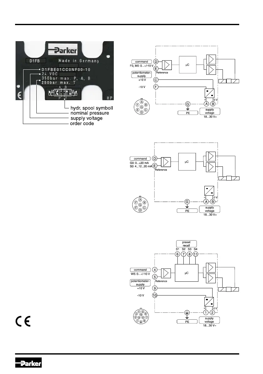
Name Plate Example Block Diagram of Integral Electronics
Code F0/M0 (6+PE)
Code S0/G0 (6+PE)
Code W5 (11+PE)

 Loading...


