Page 27
Positioner Replacement
WARNING: Failure to depressurize the system could result in injury. Disassembly of the actuator is not required. If the
positioner is inoperable, contact Parker concerning replacement of the unit.
1. Depressurize the system.
2. Turn off supply voltage and signal to the positioner. Remove electrical connectors from positioner.
3. Ensure that the pilot air supply is turned off. Remove the pilot air supply line from port “P”. Remove the actuator supply
line from port “A”.
4. Remove the pilot air supply line (tubing) from the positioner to the actuator housing.
5. Remove the positioner from the actuator housing by rotating the positioner counterclockwise.
6. Verify that the stroke range and the screw thread size of the replacement positioner matches that of the valve actuator
housing.
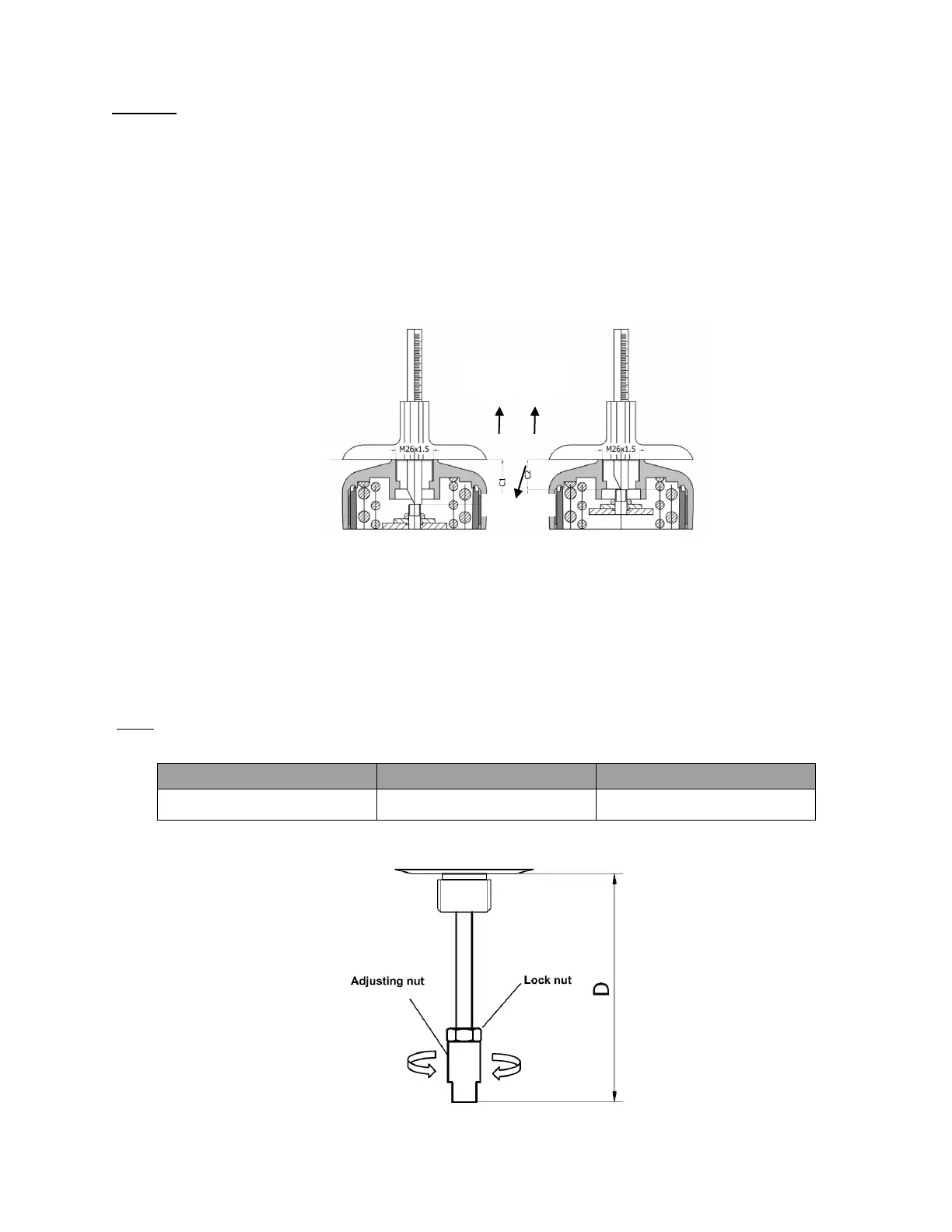
7. Separately measure the C1 value when the valve is fully closed and C2 value when the valve is fully open with a depth
gage. The values are the distance between the end of the stem and the machined face on the top of the actuator, as
shown in Figure 31.
Valve is fully closed Valve is fully open
Figure 30. Actuator measurement
8. Adjust the adjusting nut of the displacement sensor. Then measure the D value, as shown in Figure 31, with a depth gage
when the displacement sensor is completely loosened. Calculate the compression value L1 = D – C1, L2 = D – C2. It is
recommended that the compression values L1 and L2 are both in the reference range shown in Table 10. If the L1 value
or L2 value does not fall within the reference range, adjust the D value according to the actual situation.
NOTE
:
The adjusted D value must ensure that L1
>
0 and L2
<
the maximum compression value of the displacement sensor,
otherwise, the positioner cannot match the valve actuator.
2.22~2.46 in
56.5~62.5 mm
Table 10. The reference range of the compression value
Figure 31. Displacement sensor adjustment and measurement
of the actuator
 Loading...


