36
6.2
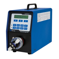
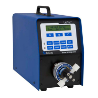
FMI Pump Heads: Installation
The following are directions to mount a FMI pump head on a LabTec™ controller. If you purchased
the LabTec™ controller with a FMI pump head already mounted, you can disregard these
directions. However, if you purchased your FMI pump head separately, you will need to mount the
pump head. The same instructions should also be used when dismounting an old pump head,
which you may want to replace with a new one:
1.
Disconnect the power cable from the LabTec™.
2.
Remove the two screws (6-32 x ½¨) from the underside of the LabTec™. These hold the motor
mounting plate in place.
3.
Remove the four (6-32 x 3/8¨) Philip screws from the faceplate at the front of the LabTec™.
4.
Carefully remove the pump / motor subassembly from the LabTec
®
controller. Disconnect
the motor cable (cable connecting the motor to the electronic board) before completely
removing the pump / motor assembly from the LabTec™ controller.
5.
Mate the FMI pump head shaft to the flexible pump motor coupling. Fasten the shaft to the
coupling (the set screw on the coupling requires a 3/32 hex bit).
6.
Fasten the FMI pump head with two screws (8-32 x ½”) to the back of the faceplate
(use an offset screwdriver).
7.
Reconnect the pump motor cable and carefully place the pump / motor assembly back into
the LabTec™ controller.
8.
Fasten the faceplate of the pump / motor assembly to the chassis with the four screws
removed in Step 3.
9.
Fasten the motor mounting plate to the underside of the LabTec™ with the two screws
removed in Step 2.
10.
Test the LabTec™ with the FMI pump head in place. Make fluid connections to the pump head.
Do not let the pump head run dry without fl id for any prolonged period of time.
6.3
FMI Pump Heads: Stroke Volume Adjustment
The knurled adjustment ring (black decal with markings, not the small knurled knob) on the FMI
pump head controls the stroke length and thus controls the output per motor revolution.
The adjustment ring is factory set at “200,” however, by turning the Adjustment Ring clockwise;
the stroke length and the pump output are reduced. However, do not turn the Adjustment Ring
below “50”. When turning the adjustment ring counter clock-wise from “50” to “450”, the
maximum stroke length / volume is obtained. Do not turn the adjustment ring above the
“450” setting.
The maximum stroke volume for the RHOO pump head is 25 μl, for the RHO pump head the stroke
volume is 50 μl while the RH1 pump head has a maximum stroke vole of 100 μl.