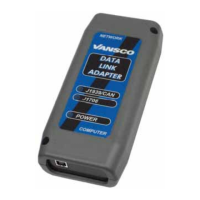
USB Data Link Adapter 20
Software Tools for the USB-DLA
J1708/J1587 Tx Count Number of J1708 messages transmitted by DLA
J1708/J1587 Rx Count Number of J1708 messages received by DLA
Adapter Packets Tx Count Number of packets transmitted by DLA to the PC
Adapter Packets Rx Count Number of packets received by DLA from the PC
Adapter Packet Errors Number of packet errors detected by the DLA
Adapter Checksum Errors Number of packet checksum errors
Vapi Server Packets Tx
Count
Number of packets transmitted by the PC to the DLA
Vapi Server Packets Rx
Count
Number of packets received by the PC from the DLA
Vapi Server Packets Errors Number of packet errors detected by the PC
CAN 1 Status Status of CAN 1 port. See table below
CAN 2 Status Status of CAN 2 port. See table below
J1708 Status Status of J1708 port. See table below
Other Status Status of optional port. See table below
Client Threads Number of clients
A status byte is associated with each of the vehicle ports on the DLA. The status byte
is displayed in hex format with each of the bits representing the following table.
Table 3: Status byte
Bit 7 reserved
Bit 6 reserved
Bit 5 reserved
Bit 4 reserved
Bit 3 Set to 1 when the data link is in the BUS OFF state (if applicable).
Bit 2 Set to 1 when traffic has been detected on the data link.
Bit 1 Set to 1 when the data link is enabled.
Bit 0 Set to 1 when the data link is present.

 Loading...