3. ELECTRICAL INSTALLATION 23
15-way D-
type pin
reference
X2
Motor
feedback
connector
pin
Resolver Encoder
1 15 Reserved Inc Enc Z+
2 16 Reserved Inc Enc Z-
3 (twin) 7 0V 0V
4 14 REFres+ Reserved
5 (twin) 8 +5V output +5V output
6 7 0V 0V
6 13 Motor overtemp- Motor overtemp-
7 1 SIN- Inc Enc A-
8 2 SIN+ Inc Enc A+
9 4 Reserved Comm f-b A0
10 9 Motor overtemp+ Motor Overtemp+
11 12 COS- Inc Enc B-
12 11 COS+ Inc Enc B+
13 5 Reserved Comm f-b A1
14 6 Reserved Comm f-b A2
15 17 REFres- Reserved
*Note: two wires are used for the +5V supply (X2 pin 5) and two wires are used for 0V
returns (X2 pin 3), two wires are also taken from X2 pin 6.
Table 3-6. Motor Feedback Cable Wiring
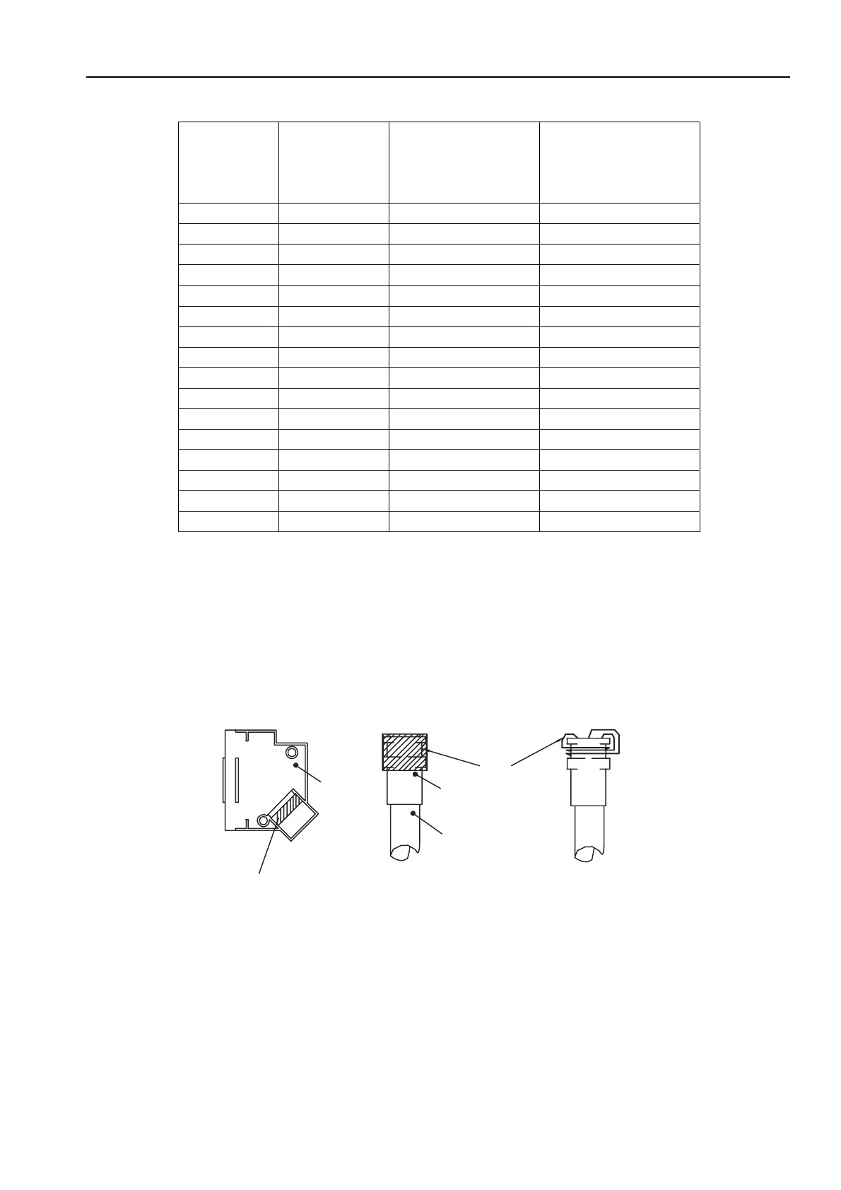
The 15-way D-type connector will require the feedback cable screen to be bonded to the
metal connector shell, as shown in Figure 3-9.
Earth bonding area
in cover
RMI earth bonding required for both connectors
cover
Example 1
Example 2
braid
ferrule
cable
Braid to be folded back over
complete cable ferrule to make
a 360° connection.
Braid to be made into 3 round
forms and wrapped a round the
recess of cable ferrule to make
a 360° connection.
Figure 3-9. Screen Bonding Methods for D-type Connectors
A ferrite absorber, with a specification matching that of the Chomerics H8FE-1115-NC, is
also required to be positioned on the feedback cable using heat shrink sleeving. The
position of the absorber should be within 150mm of the feedback connector, as shown in
Figure 3-10.
 Loading...