4. CONTROL OF VIX DRIVES 53
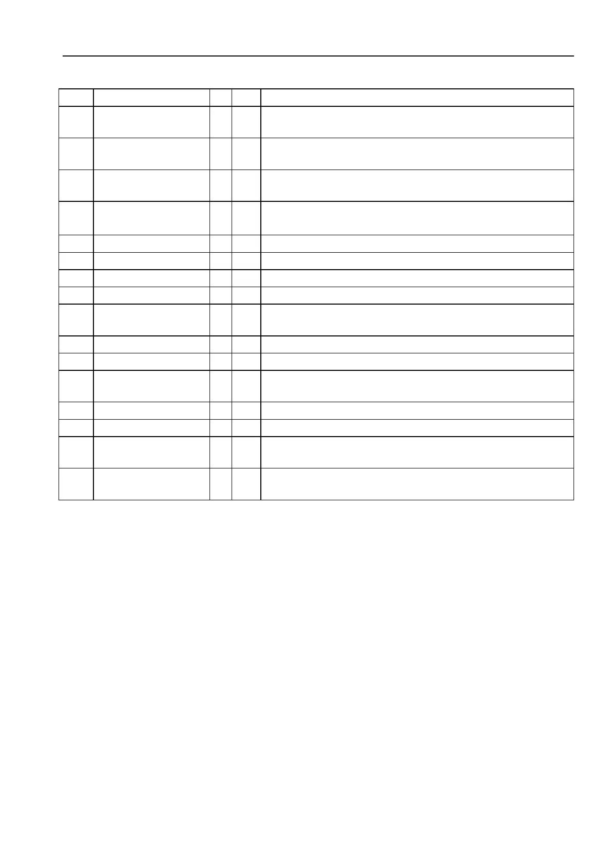
Var Name R W Range/default value
GI Integrator Gain
(steady state)
Y Y 0 to 1023 default depends on motor type
GP Proportional Gain
(stiffness)
Y Y 0 to 1023 default depends on motor type
GV Velocity feedback
Gain (damping)
Y Y 0 to 1023 default = 5
IC Input/Output
Configuration
Y Y Input pull-up/down, output source/sink configuration
0, 256 (default) or 257, for brake input only
IM Integral Mode Y Y 0=continuous (default)
IW Integral Window Y Y default 50
IX Index Pulse Y Y 0 to 1023, default=250, motor definition dependent
PA Position Actual Y N* -2,147,483,648 to 0 to 2,147,483,647, default = 0
PC Peak Current Y Y Sets maximum drive output
value=scaling factor 100-400% of MC, default=300%
PE Position Error Y N +/- 32767
PF Position Following Y Y -2,147,483,648 to 0 to 2,147,483,647, default = 0
RV ReVision of
software
Y N x.yy major.minor
SN Serial number Y N Drive serial number
ST Status of indexing Y N See Reporting the Status of Variables ST1,2,3 & 4
TL Tracking Limit Y Y 0-65535, defaults to Motor Resolution or Motor
Resolution/100 if >65535
UF User program
Fault status
Y N See Reporting of user faults UF1,2,3 & 4
*Can be set to 0 only.
Table 4-1. List of System Variables (Continued)
 Loading...