PDWE 8 B2
GB
│
IE
│
5 ■
Filling the oil mister unit
CAUTION!
► Before filling or removing the oil reservoir q
make sure that the compressed air mainte-
nance unit has been disconnected from the
compressed air source.
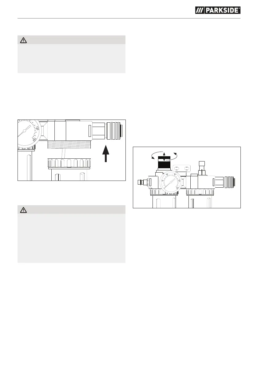
♦ Remove the oil reservoir q by turning the
locking ring 0 clockwise (see fig. E). Fill the oil
reservoir q with suitable compressor oil until
the max. marking is reached (see Fig. B).
♦ Then manually rotate the oil reservoir anticlock-
wise to the desired position q (do not use tools).
(fig. E)
Use
CAUTION!
► Ensure that the connected compressed air line
is clean and oil-free so that the compressed
air maintenance unit can be used properly.
Also make sure that the compressed air
system is pressure-free. In order to minimise
pressure losses, it is preferable to keep the
compressed air lines as short as possible.
♦ Connect the compressed air maintenance unit
to the compressed air source.
♦ First release the locking device by pulling the
air pressure regulator 3 upwards (see Fig. F).
♦ Set the air pressure regulator 3 to the lowest
setting by rotating it anticlockwise. The desired
settings are adopted by pressing the air
pressure regulator 3 downwards.
♦ Connect the compressed air supply line of the
tool to be connected to the quick coupling 8
(on the right side – output) of the compressed
air maintenance unit. A triangle "▸" on the
surface of the unit indicates the flow direction
of the compressed air.
♦ Connect the compressed air supply line of
the compressed air source via the connector
nipple 2 (on the left side inlet) of the compressed
air maintenance unit. A triangle "▸" is marked
on the surface in close proximity to the inlet,
which indicates the flow direction of the
compressed air.
(fig. F)
♦ Before using the compressed air maintenance
unit, check the direction of the compressed air
flow using the "▸" mark on the surface. Incorrect
installation will not generate sufficient pressure.
 Loading...