9
EN
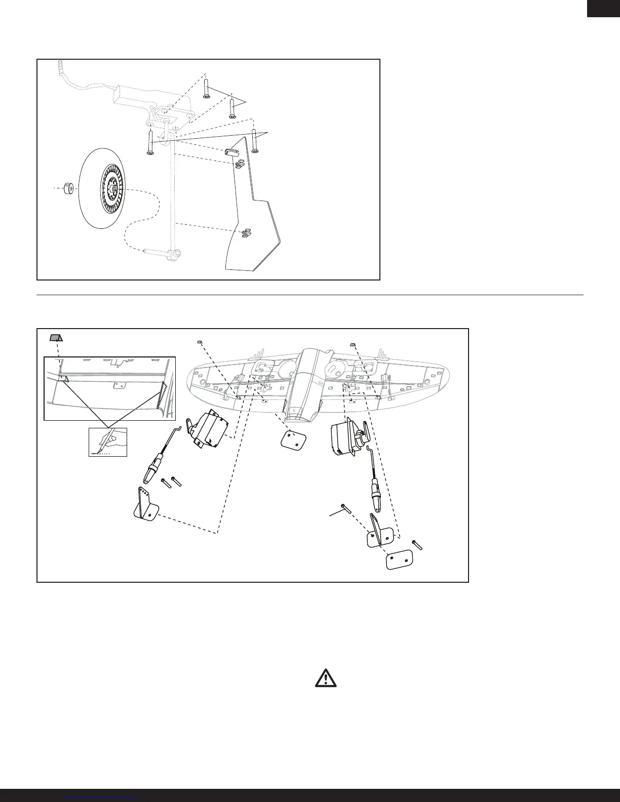
Optional Retractable Landing Gear
Removexedlandinggearmountandreuse
existingparts(seeillustration)toinstalloptional
retractablelandinggear(EFLG100,soldsepa-
rately).Seeinstallationinstructionsincludedwith
optional landing gear.
Note:Theshortscrews(M3x15)areinstalledin
the two front holes.
Note: Not to scale. Y-harness is not shown.
Optional Flaps
1. Remove wing from fuselage.
2. Installleftandrightapservo(PKZ1081x2,soldseparately)inpocket
using hot glue or double-sided tape.
3. Installleftandrightcontrolhornandplateonwingusing2screws.
4. Carefully cut wedge of foam from flap hinge near aileron hinge
(seeillustration).
5. Carefully cut small amount of foam at flap and wing root so flap moves
freely(seeillustration).
6. Movetapetoputservowiresinwingchannel.
7. Put flap servo wire in wing channel with aileron wire.
8. Put flap servo connector in hole at wing root.
9. Put tape over channel.
10. Cut a small amount of tape at flap servo to let servo arm move freely.
11. Install connector and clevis in outer hole in servo arm and outer hole in
control horn.
12. Adjust clevis so flap is not pulled fully against the wing at the hinge when
flap is operated.
13. Enableapoperationonrightsideofwingusingtheseinstructions.
14. Put servo connectors in fuselage.
15. Attach wing to fuselage.
CAUTION:Makesurewiresarenotcrushed,orotherwisedamaged,
when wing is attached to fuselage.
16. Attach servo connectors to correct receiver channels or Y-harnesses.
17. Do a control test of flaps using your aircraft and transmitter.
Note: Disconnect the clevis from the flap control horn when initially setting up
the flaps to avoid potentially binding the control surface during setup.
Note: Not to scale. Wiring is not
shown. Tape is not shown.
Strut Length: 130mm
 Loading...