3. Connectors
3.1 Interface Connectors
Refer to Section 2.1, Interface
3.2 Electrical Characteristics
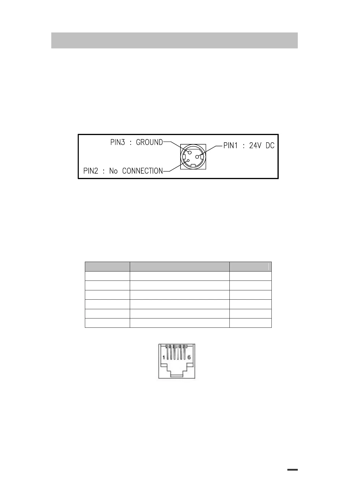
1) Input Voltage: DC 24V ± 10%
2) Current Consumption: Operating: Approx. 1.5 A (at ASC∥ printing)
Peak: Approx. 10 A (at print duty 100%, For 10 seconds or less)
Stand-by: Approx. 0.03 A
3) Power Connector
3.3 Drawer Kick-out Connector (Modular Connector)
The pulse specified by ESC p or DLE DC4 is output to this connector.
The host can confirm the status of the input signal by using the
DLE EOT, GS a, or GS r commands.
1) Pin assignments: Refer to Table 2.2.2
2) Connector model:
Printer side: DAEEUN DEK-623PCB-6-B or Equivalent
User side: 6-position 6-contact (RJ12telephone jack)
< Drawer Kick-out Connector Pin Assignments >
Drawer kick-out drive signal 1
Drawer kick-out drive signal 2
+24V is output through pin 4 when the power is turned on. However, pin 4 must by used only for the drawer.
< Figure 3.1 Drawer Kick-out Connector >
3) Drawer kick-out drive signal
Output signal: Output voltage: Approximately 24V
Output current: 1A or less